Empower your projects with reliable, rapid charging capabilities using MAX1811 and PIC32MZ2048EFH100
Energize your life with our Li-Ion charger!

Published Nov 15, 2023
Click board™
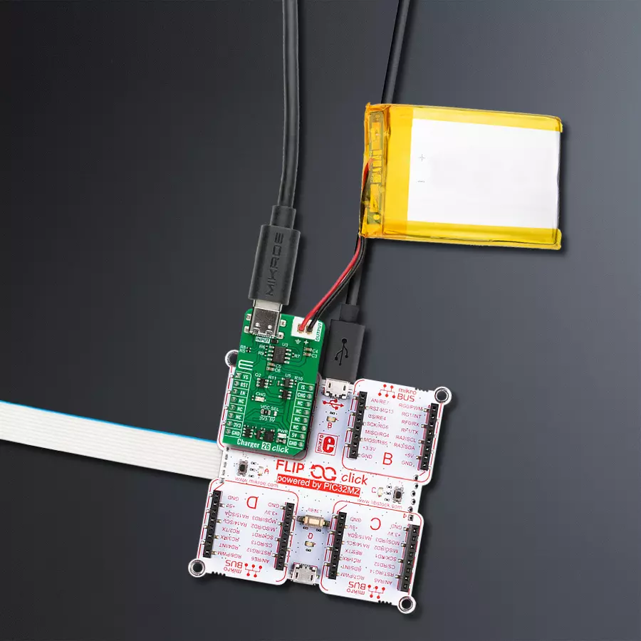
Charger 26 Click
Dev. board
Flip&Click PIC32MZ
Compiler
NECTO Studio
MCU
PIC32MZ2048EFH100
Discover a new standard in charging efficiency as our Li+ charger seamlessly blend speed and reliability, ensuring your devices are always primed for the demands of your dynamic lifestyle.
A
A
Hardware Overview
How does it work?
Charger 26 Click is based on the MAX1811, a USB-powered Li+ charger from Analog Devices. The voltage/current regulator of the MAX1811 consists of a voltage control loop, a current control loop, and a thermal control loop. The charger allows you to set the battery regulation voltage to a 4.1V or 4.2 single Li+ cell. It also allows you to set the battery's charging current in either 100mA or 500mA modes. You should note that by charging the battery over the powered USB host, you can select a 500mA mode. An unpowered USB hub is limited to only 100mA. Charger 26 Click is equipped with circuits that will recognize if the MAX1811 is powered over the USB. If not, the MAX1811 will be powered over the 5V mikroBUS™ socket rail. This circuit consists of the MAX40200, an ultra-tiny micropower 1A ideal diode with
ultra-low voltage drop from Analog Devices, which will hold the 5V rail if there is a VUSB presence. The SN74AHC1G08, a single 2-input positive-AND gate from Texas Instruments, is here to prevent the MAX1811 charger from being powered from the UCB C input connector if the Charger 26 Click is not connected to a development board equipped with the mikroBUS™ socket. The CHG orange LED is here to indicate the charge status. You can connect the single Li+ cell battery over the JST output connector. Before you do so, please double-check the polarity of the battery. Charger 26 Click uses the GPIO to communicate with the host MCU. You can select a battery regulation voltage over the VS pin, which, with a pull-up resistor, is set to a 4.2V battery regulation set point. You can also select a battery
regulation current over the IS pin, which, with a pull-down resistor, is set to 100mA maximum battery regulation current. Besides the CHG LED, the charging status can be monitored over the CHG output pin. The enable EN pin controls the enable input of the MAX1811 charger, which is enabled by default by the pull-up resistor. This Click board™ can operate with either 3.3V or 5V logic voltage levels selected via the VCC SEL jumper. This way, both 3.3V and 5V capable MCUs can use the communication lines properly. Also, this Click board™ comes equipped with a library containing easy-to-use functions and an example code that can be used as a reference for further development.

Features overview
Development board
Flip&Click PIC32MZ is a compact development board designed as a complete solution that brings the flexibility of add-on Click boards™ to your favorite microcontroller, making it a perfect starter kit for implementing your ideas. It comes with an onboard 32-bit PIC32MZ microcontroller, the PIC32MZ2048EFH100 from Microchip, four mikroBUS™ sockets for Click board™ connectivity, two USB connectors, LED indicators, buttons, debugger/programmer connectors, and two headers compatible with Arduino-UNO pinout. Thanks to innovative manufacturing technology,
it allows you to build gadgets with unique functionalities and features quickly. Each part of the Flip&Click PIC32MZ development kit contains the components necessary for the most efficient operation of the same board. In addition, there is the possibility of choosing the Flip&Click PIC32MZ programming method, using the chipKIT bootloader (Arduino-style development environment) or our USB HID bootloader using mikroC, mikroBasic, and mikroPascal for PIC32. This kit includes a clean and regulated power supply block through the USB Type-C (USB-C) connector. All communication
methods that mikroBUS™ itself supports are on this board, including the well-established mikroBUS™ socket, user-configurable buttons, and LED indicators. Flip&Click PIC32MZ development kit allows you to create a new application in minutes. Natively supported by Mikroe software tools, it covers many aspects of prototyping thanks to a considerable number of different Click boards™ (over a thousand boards), the number of which is growing every day.

Microcontroller Overview
MCU Card / MCU

Architecture
PIC32
MCU Memory (KB)
2048
Silicon Vendor
Microchip
Pin count
100
RAM (Bytes)
524288
You complete me!
Accessories
Li-Polymer Battery is the ideal solution for devices that demand a dependable and long-lasting power supply while emphasizing mobility. Its compatibility with mikromedia boards ensures easy integration without additional modifications. With a voltage output of 3.7V, the battery meets the standard requirements of many electronic devices. Additionally, boasting a capacity of 2000mAh, it can store a substantial amount of energy, providing sustained power for extended periods. This feature minimizes the need for frequent recharging or replacement. Overall, the Li-Polymer Battery is a reliable and autonomous power source, ideally suited for devices requiring a stable and enduring energy solution. You can find a more extensive choice of Li-Polymer batteries in our offer.

Used MCU Pins
mikroBUS™ mapper
Take a closer look
Click board™ Schematic

Step by step
Project assembly

Start by selecting your development board and Click board™. Begin with the Flip&Click PIC32MZ as your development board.


Software Support
Library Description
This library contains API for Charger 26 Click driver.
Key functions:
charger26_set_vsel- Charger 26 select charger voltage function.charger26_set_isel- Charger 26 select charger current function.charger26_get_chg_state- Charger 26 chg pin reading function.
Open Source
Code example
The complete application code and a ready-to-use project are available through the NECTO Studio Package Manager for direct installation in the NECTO Studio. The application code can also be found on the MIKROE GitHub account.
/*!
 * @file main.c
 * @brief Charger 26 Click Example.
 *
 * # Description
 * This example demonstrates the use of Charger 26 Click board by enabling the device
 * and then reading and displaying the charger status.
 *
 * The demo application is composed of two sections :
 *
 * ## Application Init
 * Initializes the driver and enables the device, sets the output
 * voltage to 4.2 V and charging current to 100 mA.
 *
 * ## Application Task
 * Tracking charging status, as soon as charging stops, device output is disabled.
 *
 * @author Stefan Ilic
 *
 */

#include "board.h"
#include "log.h"
#include "charger26.h"

static charger26_t charger26;   /**< Charger 26 Click driver object. */
static log_t logger;    /**< Logger object. */

void application_init ( void )
{
    log_cfg_t log_cfg;  /**< Logger config object. */
    charger26_cfg_t charger26_cfg;  /**< Click config object. */

    /**
     * Logger initialization.
     * Default baud rate: 115200
     * Default log level: LOG_LEVEL_DEBUG
     * @note If USB_UART_RX and USB_UART_TX
     * are defined as HAL_PIN_NC, you will
     * need to define them manually for log to work.
     * See @b LOG_MAP_USB_UART macro definition for detailed explanation.
     */
    LOG_MAP_USB_UART( log_cfg );
    log_init( &logger, &log_cfg );
    log_info( &logger, " Application Init " );

    // Click initialization.
    charger26_cfg_setup( &charger26_cfg );
    CHARGER26_MAP_MIKROBUS( charger26_cfg, MIKROBUS_1 );
    if ( DIGITAL_OUT_UNSUPPORTED_PIN == charger26_init( &charger26, &charger26_cfg ) )
    {
        log_error( &logger, " Communication init." );
        for ( ; ; );
    }

    charger26_default_cfg ( &charger26 );
    Delay_ms ( 1000 );

    log_printf( &logger, " Connect input power and battery. \r\n" );
    Delay_ms ( 1000 );
    Delay_ms ( 1000 );
    Delay_ms ( 1000 );
    Delay_ms ( 1000 );
    Delay_ms ( 1000 );
    log_printf( &logger, " Enableing output. \r\n" );
    charger26_enable_output ( &charger26, CHARGER26_ENABLE_OUTPUT );

    while ( CHARGER26_PIN_STATE_LOW != charger26_get_chg_state( &charger26 ) )
    {
        log_printf( &logger, " Check connection. \r\n" );
        Delay_ms ( 1000 );
    }

    log_info( &logger, " Application Task " );
}

void application_task ( void )
{
    if ( CHARGER26_PIN_STATE_LOW == charger26_get_chg_state( &charger26 ) )
    {
        log_printf( &logger, " Battery is charging. \r\n" );
    }
    else
    {
        log_printf( &logger, " Battery isn't charging, disabling output. \r\n" );
        charger26_enable_output ( &charger26, CHARGER26_DISABLE_OUTPUT );
        for ( ; ; );
    }
    Delay_ms ( 1000 );
}

int main ( void )
{
    /* Do not remove this line or clock might not be set correctly. */
    #ifdef PREINIT_SUPPORTED
    preinit();
    #endif

    application_init( );

    for ( ; ; )
    {
        application_task( );
    }

    return 0;
}

// ------------------------------------------------------------------------ END
Additional Support
Resources
Category:Battery charger


