Create USB management and charging solution with LTC3553 and STM32F031K6
Recharge and thrive

Published Oct 01, 2024
Click board™
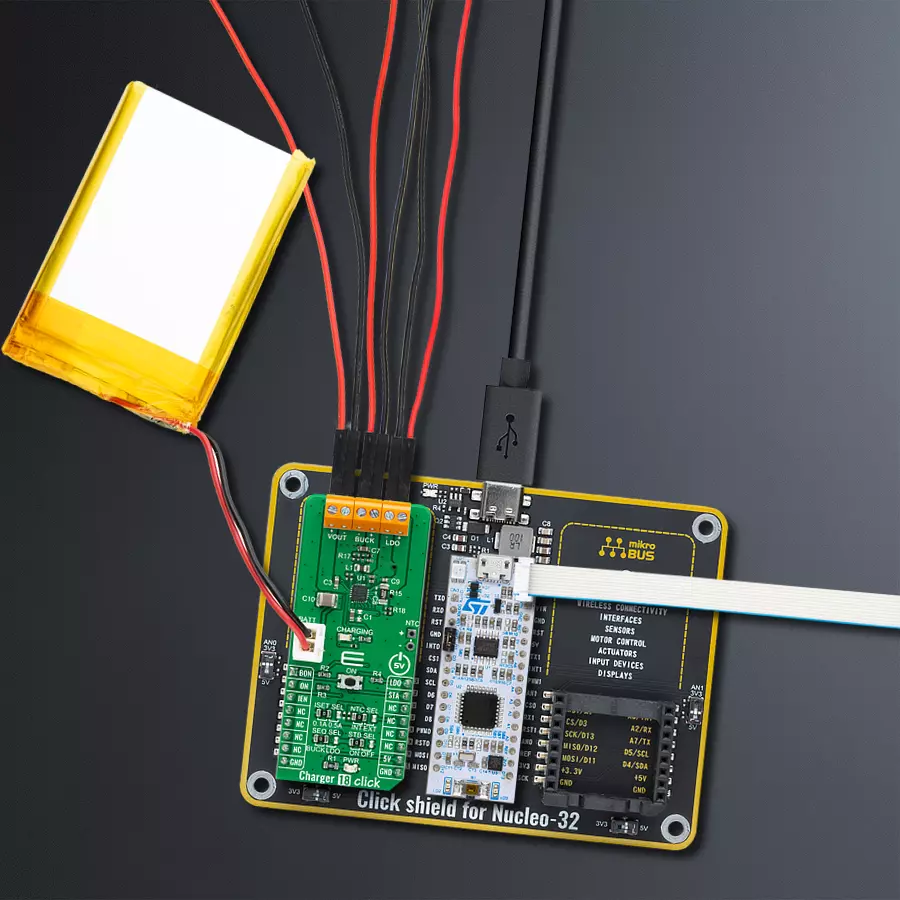
Charger 18 Click
Dev. board
Nucleo 32 with STM32F031K6 MCU
Compiler
NECTO Studio
MCU
STM32F031K6
Don't wait for your battery to run out - choose a fast-charging battery charger and stay powered up all day
A
A
Hardware Overview
How does it work?
Charger 18 Click is based on the LTC3553, a micropower multifunction power management integrated circuit (PMIC) for portable Li-Ion/Polymer battery-based applications from Analog Devices. It combines a USB-compatible PowerPath manager with automatic load prioritization delivering up to 400mA battery charge current from a 5V USB input. The device’s ‘instant-on’ operation ensures immediate system load power when a USB supply is available, even with a fully discharged battery. Alongside a stand-alone battery charger, it has a high-efficiency synchronous 200mA buck regulator and a 150mA low dropout linear regulator available on the onboard connectors. This Click board™ has an input current limit selection allowing the user to select between 100mA and 500mA input current limit. The choice can be made by appropriately positioning the SMD jumper labeled ISET SEL. Besides ISET, it also possesses SEQ SEL jumper selection determining which regulator is enabled before the other. The first-regulator power-up selection is made by positioning this SMD jumper to an appropriate position
marked as BUCK or LDO. On the other hand, the BON and LDO pins routed to the AN and PWM pins on the mikroBUS™ socket enable the buck and LDO regulators by setting these pins to a high logic state. Alongside these pins, the LTC3553 also includes a pushbutton input to control the two regulators and system reset - an onboard pushbutton labeled ON, also routed to the RST pin on the mikroBUS™, representing the Regulator Ignition button. Pressing the button causes an STA interrupt, informing the MCU that this event has occurred. These regulators are also related to a Standby Mode, selectable through an SMD jumper labeled as ISET SEL. When this jumper is placed ON, the buck and the LDO regulator quiescent current is reduced to low levels while maintaining output voltage regulation. The buck regulator is limited to a 10mA maximum load current in this mode, and the LDO regulator’s response to line and load transients is slower. As already mentioned in the text, this Click board™ communicates with MCU using several GPIO pins. With the IEN pin routed to the CS pin on the
mikroBUS™ socket pulled high, the LTC3553 enters Suspend mode to comply with the USB specification. In this mode, the power path between USB and VOUT is put in a high impedance state to reduce the USB input current. This Click board™ also comes with a blue LED labeled CHARGING for the battery charging state. An NTC function is also available for temperature-qualified charging. The temperature monitoring feature is selectable via an NTC SEL jumper, where the user can choose between external or internal monitoring modes. A negative temperature coefficient (NTC) thermistor input for the battery temperature monitor is provided for the external mode. This Click board™ can only be operated with a 5V logic voltage level. The board must perform appropriate logic voltage level conversion before using MCUs with different logic levels. However, the Click board™ comes equipped with a library containing functions and an example code that can be used as a reference for further development.

Features overview
Development board
Nucleo 32 with STM32F031K6 MCU board provides an affordable and flexible platform for experimenting with STM32 microcontrollers in 32-pin packages. Featuring Arduino™ Nano connectivity, it allows easy expansion with specialized shields, while being mbed-enabled for seamless integration with online resources. The
board includes an on-board ST-LINK/V2-1 debugger/programmer, supporting USB reenumeration with three interfaces: Virtual Com port, mass storage, and debug port. It offers a flexible power supply through either USB VBUS or an external source. Additionally, it includes three LEDs (LD1 for USB communication, LD2 for power,
and LD3 as a user LED) and a reset push button. The STM32 Nucleo-32 board is supported by various Integrated Development Environments (IDEs) such as IAR™, Keil®, and GCC-based IDEs like AC6 SW4STM32, making it a versatile tool for developers.

Microcontroller Overview
MCU Card / MCU

Architecture
ARM Cortex-M0
MCU Memory (KB)
32
Silicon Vendor
STMicroelectronics
Pin count
32
RAM (Bytes)
4096
You complete me!
Accessories
Click Shield for Nucleo-32 is the perfect way to expand your development board's functionalities with STM32 Nucleo-32 pinout. The Click Shield for Nucleo-32 provides two mikroBUS™ sockets to add any functionality from our ever-growing range of Click boards™. We are fully stocked with everything, from sensors and WiFi transceivers to motor control and audio amplifiers. The Click Shield for Nucleo-32 is compatible with the STM32 Nucleo-32 board, providing an affordable and flexible way for users to try out new ideas and quickly create prototypes with any STM32 microcontrollers, choosing from the various combinations of performance, power consumption, and features. The STM32 Nucleo-32 boards do not require any separate probe as they integrate the ST-LINK/V2-1 debugger/programmer and come with the STM32 comprehensive software HAL library and various packaged software examples. This development platform provides users with an effortless and common way to combine the STM32 Nucleo-32 footprint compatible board with their favorite Click boards™ in their upcoming projects.

Li-Polymer Battery is the ideal solution for devices that demand a dependable and long-lasting power supply while emphasizing mobility. Its compatibility with mikromedia boards ensures easy integration without additional modifications. With a voltage output of 3.7V, the battery meets the standard requirements of many electronic devices. Additionally, boasting a capacity of 2000mAh, it can store a substantial amount of energy, providing sustained power for extended periods. This feature minimizes the need for frequent recharging or replacement. Overall, the Li-Polymer Battery is a reliable and autonomous power source, ideally suited for devices requiring a stable and enduring energy solution. You can find a more extensive choice of Li-Polymer batteries in our offer.

Used MCU Pins
mikroBUS™ mapper
Take a closer look
Click board™ Schematic

Step by step
Project assembly

Start by selecting your development board and Click board™. Begin with the Nucleo 32 with STM32F031K6 MCU as your development board.


Software Support
Library Description
This library contains API for Charger 18 Click driver.
Key functions:
charger18_buck_controlThis function controls the buck regulator and enables the state of the Charger 18 Click board™.charger18_ldo_controlThis function controls the low dropout (LDO) regulator to enable the state of the Charger 18 Click board™.charger18_suspend_controlThis function controls the suspend charging mode state of the Charger 18 Click board™.
Open Source
Code example
The complete application code and a ready-to-use project are available through the NECTO Studio Package Manager for direct installation in the NECTO Studio. The application code can also be found on the MIKROE GitHub account.
/*!
 * @file main.c
 * @brief Charger 18 Click Example.
 *
 * # Description
 * This example demonstrates the use of Charger 18 Click board by controlling
 * the status of the charger as well as the LDO and BUCK regulators.
 *
 * The demo application is composed of two sections :
 *
 * ## Application Init
 * Initializes the driver and enables the chip with the charger, LDO and BUCK regulators disabled.
 *
 * ## Application Task
 * This function enables the charger, BUCK and LDO in the span of 25 seconds, and displays
 * the status of each feature on the USB UART.
 *
 * @author Stefan Filipovic
 *
 */

#include "board.h"
#include "log.h"
#include "charger18.h"

static charger18_t charger18;   /**< Charger 18 Click driver object. */
static log_t logger;    /**< Logger object. */

void application_init ( void )
{
    log_cfg_t log_cfg;  /**< Logger config object. */
    charger18_cfg_t charger18_cfg;  /**< Click config object. */

    /**
     * Logger initialization.
     * Default baud rate: 115200
     * Default log level: LOG_LEVEL_DEBUG
     * @note If USB_UART_RX and USB_UART_TX
     * are defined as HAL_PIN_NC, you will
     * need to define them manually for log to work.
     * See @b LOG_MAP_USB_UART macro definition for detailed explanation.
     */
    LOG_MAP_USB_UART( log_cfg );
    log_init( &logger, &log_cfg );
    log_info( &logger, " Application Init " );

    // Click initialization.
    charger18_cfg_setup( &charger18_cfg );
    CHARGER18_MAP_MIKROBUS( charger18_cfg, MIKROBUS_1 );
    if ( DIGITAL_OUT_UNSUPPORTED_PIN == charger18_init( &charger18, &charger18_cfg ) )
    {
        log_error( &logger, " Communication init." );
        for ( ; ; );
    }

    charger18_power_control( &charger18, CHARGER18_CONTROL_ENABLE );
    log_printf( &logger, " POWER   : ON\r\n" );
    charger18_suspend_control( &charger18, CHARGER18_CONTROL_ENABLE );
    log_printf( &logger, " CHARGER : OFF\r\n" );
    charger18_buck_control( &charger18, CHARGER18_CONTROL_DISABLE );
    log_printf( &logger, " BUCK    : OFF\r\n" );
    charger18_ldo_control( &charger18, CHARGER18_CONTROL_DISABLE );
    log_printf( &logger, " LDO     : OFF\r\n" );

    log_info( &logger, " Application Task " );
}

void application_task ( void )
{
    charger18_suspend_control( &charger18, CHARGER18_CONTROL_DISABLE );
    log_printf( &logger, " CHARGER : ON\r\n" );
    // 10 seconds delay
    Delay_ms ( 1000 );
    Delay_ms ( 1000 );
    Delay_ms ( 1000 );
    Delay_ms ( 1000 );
    Delay_ms ( 1000 );
    Delay_ms ( 1000 );
    Delay_ms ( 1000 );
    Delay_ms ( 1000 );
    Delay_ms ( 1000 );
    Delay_ms ( 1000 );
    charger18_suspend_control( &charger18, CHARGER18_CONTROL_ENABLE );
    log_printf( &logger, " CHARGER : OFF\r\n" );
    Delay_ms ( 1000 );
    Delay_ms ( 1000 );
    Delay_ms ( 1000 );
    charger18_buck_control( &charger18, CHARGER18_CONTROL_ENABLE );
    log_printf( &logger, " BUCK    : ON\r\n" );
    Delay_ms ( 1000 );
    Delay_ms ( 1000 );
    Delay_ms ( 1000 );
    charger18_buck_control( &charger18, CHARGER18_CONTROL_DISABLE );
    log_printf( &logger, " BUCK    : OFF\r\n" );
    Delay_ms ( 1000 );
    Delay_ms ( 1000 );
    Delay_ms ( 1000 );
    charger18_ldo_control( &charger18, CHARGER18_CONTROL_ENABLE );
    log_printf( &logger, " LDO     : ON\r\n" );
    Delay_ms ( 1000 );
    Delay_ms ( 1000 );
    Delay_ms ( 1000 );
    charger18_ldo_control( &charger18, CHARGER18_CONTROL_DISABLE );
    log_printf( &logger, " LDO     : OFF\r\n\n" );
    Delay_ms ( 1000 );
    Delay_ms ( 1000 );
    Delay_ms ( 1000 );
}

int main ( void )
{
    /* Do not remove this line or clock might not be set correctly. */
    #ifdef PREINIT_SUPPORTED
    preinit();
    #endif

    application_init( );

    for ( ; ; )
    {
        application_task( );
    }

    return 0;
}

// ------------------------------------------------------------------------ END
Additional Support
Resources
Category:Battery charger


