Revitalize your batteries with TP4056 and STM32F410RB
Empower your devices

Published Oct 08, 2024
Click board™
Charger 3 Click
Dev. board
Nucleo 64 with STM32F410RB MCU
Compiler
NECTO Studio
MCU
STM32F410RB
Incorporate an innovative battery charger into your solution and stay ahead of the competition
A
A
Hardware Overview
How does it work?
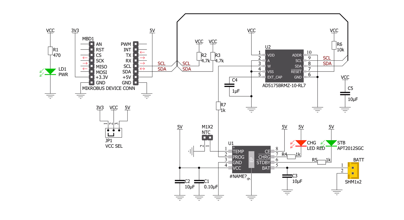
Charger 3 Click is based on the TP4056, a complete constant-current/constant-voltage linear charger for single-cell lithium-ion batteries from NanJing Top Power ASIC Corp. This standalone battery charger automatically terminates the charge cycle when the charge current drops to 1/10th of the programmed value after reaching the final float voltage. Thermal feedback regulates the charging current to limit the die temperature during high power operation or high ambient temperature. It also features current monitoring, under-voltage lockout, automatic recharge, and two LEDs to indicate charge termination and the presence of an input voltage. The charge voltage of the TP4056 is specified at 4.2V with 1.5%
accuracy, with the charge current pin programmableup to 1000mA via an onboard single-channel digital potentiometer, the AD5175 from Analog Devices, controllable through the I2C compatible digital interface. When the TP4056 is in a pre-charge mode, this pins voltage is regulated to 0.2V, while in the constant-charge current mode, voltage is regulated to 2V. During the charging process, the voltage on this pin can be used to measure the charge current. Charger 3 Click also has the possibility of connecting an external temperature sensor on the onboard header labeled as NTC. If the voltage of this pin is below 45% or above 80% of the supply voltage for more than 0.15s, the battery’s temperature is too high or too low,
suspending the charging process. Alongside this feature, this Click board™ also has two LEDs to indicate charge termination and the presence of an input voltage, a red LED labeled CHG indicating the charging process, and a green LED labeled STB for fully-charged status. This Click board™ can operate with either 3.3V or 5V logic voltage levels selected via the VCC SEL jumper. This way, both 3.3V and 5V capable MCUs can use the communication lines properly. However, the Click board™ comes equipped with a library containing easy-to-use functions and an example code that can be used, as a reference, for further development.

Features overview
Development board
Nucleo-64 with STM32F410RB MCU offers a cost-effective and adaptable platform for developers to explore new ideas and prototype their designs. This board harnesses the versatility of the STM32 microcontroller, enabling users to select the optimal balance of performance and power consumption for their projects. It accommodates the STM32 microcontroller in the LQFP64 package and includes essential components such as a user LED, which doubles as an ARDUINO® signal, alongside user and reset push-buttons, and a 32.768kHz crystal oscillator for precise timing operations. Designed with expansion and flexibility in mind, the Nucleo-64 board features an ARDUINO® Uno V3 expansion connector and ST morpho extension pin
headers, granting complete access to the STM32's I/Os for comprehensive project integration. Power supply options are adaptable, supporting ST-LINK USB VBUS or external power sources, ensuring adaptability in various development environments. The board also has an on-board ST-LINK debugger/programmer with USB re-enumeration capability, simplifying the programming and debugging process. Moreover, the board is designed to simplify advanced development with its external SMPS for efficient Vcore logic supply, support for USB Device full speed or USB SNK/UFP full speed, and built-in cryptographic features, enhancing both the power efficiency and security of projects. Additional connectivity is
provided through dedicated connectors for external SMPS experimentation, a USB connector for the ST-LINK, and a MIPI® debug connector, expanding the possibilities for hardware interfacing and experimentation. Developers will find extensive support through comprehensive free software libraries and examples, courtesy of the STM32Cube MCU Package. This, combined with compatibility with a wide array of Integrated Development Environments (IDEs), including IAR Embedded Workbench®, MDK-ARM, and STM32CubeIDE, ensures a smooth and efficient development experience, allowing users to fully leverage the capabilities of the Nucleo-64 board in their projects.

Microcontroller Overview
MCU Card / MCU

Architecture
ARM Cortex-M4
MCU Memory (KB)
128
Silicon Vendor
STMicroelectronics
Pin count
64
RAM (Bytes)
32768
You complete me!
Accessories
Click Shield for Nucleo-64 comes equipped with two proprietary mikroBUS™ sockets, allowing all the Click board™ devices to be interfaced with the STM32 Nucleo-64 board with no effort. This way, Mikroe allows its users to add any functionality from our ever-growing range of Click boards™, such as WiFi, GSM, GPS, Bluetooth, ZigBee, environmental sensors, LEDs, speech recognition, motor control, movement sensors, and many more. More than 1537 Click boards™, which can be stacked and integrated, are at your disposal. The STM32 Nucleo-64 boards are based on the microcontrollers in 64-pin packages, a 32-bit MCU with an ARM Cortex M4 processor operating at 84MHz, 512Kb Flash, and 96KB SRAM, divided into two regions where the top section represents the ST-Link/V2 debugger and programmer while the bottom section of the board is an actual development board. These boards are controlled and powered conveniently through a USB connection to program and efficiently debug the Nucleo-64 board out of the box, with an additional USB cable connected to the USB mini port on the board. Most of the STM32 microcontroller pins are brought to the IO pins on the left and right edge of the board, which are then connected to two existing mikroBUS™ sockets. This Click Shield also has several switches that perform functions such as selecting the logic levels of analog signals on mikroBUS™ sockets and selecting logic voltage levels of the mikroBUS™ sockets themselves. Besides, the user is offered the possibility of using any Click board™ with the help of existing bidirectional level-shifting voltage translators, regardless of whether the Click board™ operates at a 3.3V or 5V logic voltage level. Once you connect the STM32 Nucleo-64 board with our Click Shield for Nucleo-64, you can access hundreds of Click boards™, working with 3.3V or 5V logic voltage levels.

Li-Polymer Battery is the ideal solution for devices that demand a dependable and long-lasting power supply while emphasizing mobility. Its compatibility with mikromedia boards ensures easy integration without additional modifications. With a voltage output of 3.7V, the battery meets the standard requirements of many electronic devices. Additionally, boasting a capacity of 2000mAh, it can store a substantial amount of energy, providing sustained power for extended periods. This feature minimizes the need for frequent recharging or replacement. Overall, the Li-Polymer Battery is a reliable and autonomous power source, ideally suited for devices requiring a stable and enduring energy solution. You can find a more extensive choice of Li-Polymer batteries in our offer.

Used MCU Pins
mikroBUS™ mapper
Take a closer look
Click board™ Schematic
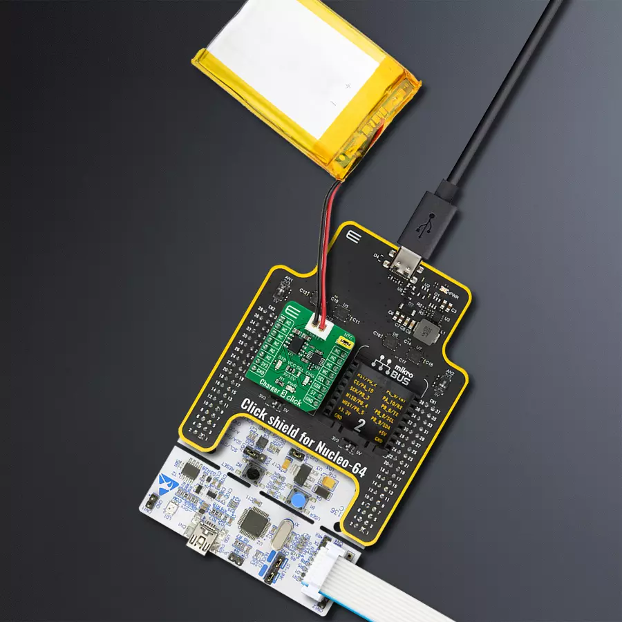
Step by step
Project assembly
Start by selecting your development board and Click board™. Begin with the Nucleo 64 with STM32F410RB MCU as your development board.


Software Support
Library Description
This library contains API for Charger 3 Click driver.
Key functions:
void charger3_cfg_setup ( charger3_cfg_t *cfg );- Config Object Initialization function.CHARGER3_RETVAL charger3_init ( charger3_t *ctx, charger3_cfg_t *cfg );- Initialization function.void charger3_default_cfg ( charger3_t *ctx );- Click Default Configuration function.
Open Source
Code example
The complete application code and a ready-to-use project are available through the NECTO Studio Package Manager for direct installation in the NECTO Studio. The application code can also be found on the MIKROE GitHub account.
/*!
 * @file main.c
 * @brief Charger3 Click example
 *
 * # Description
 * This example demonstrates the utilization of Charger 3 Click.
 *
 * The demo application is composed of two sections :
 *
 * ## Application Init
 * The application init sets up the UART LOG and I2C communication
 * drivers. The default configuration disables write protection
 * and sets the operation mode to charging.
 *
 * ## Application Task
 * Task consists of two operations. First, the desired battery
 * charging current is set by the user. Since setting the current
 * doesn't implicitly reveals the resistance, the value
 * of AD5175 digipot is directly read from the RDAC register,
 * calculated and displayed on the uart log.
 *
 * *note:*
 * While the resistance of the AD5175 can be directly set and read,
 * the total resistance value on the PROG pin should be accounted for
 * ( this means an additional 1kohm in series ) setting of the
 * battery charging current.
 *
 * @author Stefan Nikolic
 *
 */

#include "board.h"
#include "log.h"
#include "charger3.h"

static charger3_t charger3;
static log_t logger;

void application_init ( void ) {
    log_cfg_t log_cfg;  /**< Logger config object. */
    charger3_cfg_t charger3_cfg;  /**< Click config object. */

    /**
     * Logger initialization.
     * Default baud rate: 115200
     * Default log level: LOG_LEVEL_DEBUG
     * @note If USB_UART_RX and USB_UART_TX
     * are defined as HAL_PIN_NC, you will
     * need to define them manually for log to work.
     * See @b LOG_MAP_USB_UART macro definition for detailed explanation.
     */
    LOG_MAP_USB_UART( log_cfg );
    log_init( &logger, &log_cfg );
    log_info( &logger, " Application Init " );

    // Click initialization.

    charger3_cfg_setup( &charger3_cfg );
    CHARGER3_MAP_MIKROBUS( charger3_cfg, MIKROBUS_1 );
    err_t init_flag = charger3_init( &charger3, &charger3_cfg );
    if ( init_flag == I2C_MASTER_ERROR ) {
        log_error( &logger, " Application Init Error. " );
        log_info( &logger, " Please, run program again... " );

        for ( ; ; );
    }

    Delay_ms ( 100 );
    charger3_default_cfg ( &charger3 );
    log_info( &logger, " Application Task " );
    log_printf( &logger, " ------------------------------------\r\n" );
    Delay_ms ( 100 );
}

void application_task ( void ) {
    float result;

    charger3_set_current( &charger3, 0.4 );
    Delay_ms ( 1000 );
    result = charger3_calc_digipot_res( &charger3 );
    log_printf( &logger, " Digipot res value: %.2f ohm\r\n", result );
    log_printf( &logger, " ------------------------------------\r\n" );
    Delay_ms ( 1000 );
    Delay_ms ( 1000 );
    Delay_ms ( 1000 );
    Delay_ms ( 1000 );
    Delay_ms ( 1000 );
}

int main ( void )
{
    /* Do not remove this line or clock might not be set correctly. */
    #ifdef PREINIT_SUPPORTED
    preinit();
    #endif

    application_init( );

    for ( ; ; )
    {
        application_task( );
    }

    return 0;
}

// ------------------------------------------------------------------------ END
Additional Support
Resources
Category:Battery charger


