Charge into the future with BQ25601 and STM32F302VC
Plug, Charge, Conquer

Published Jul 22, 2025
Click board™
Charger 6 Click
Dev. board
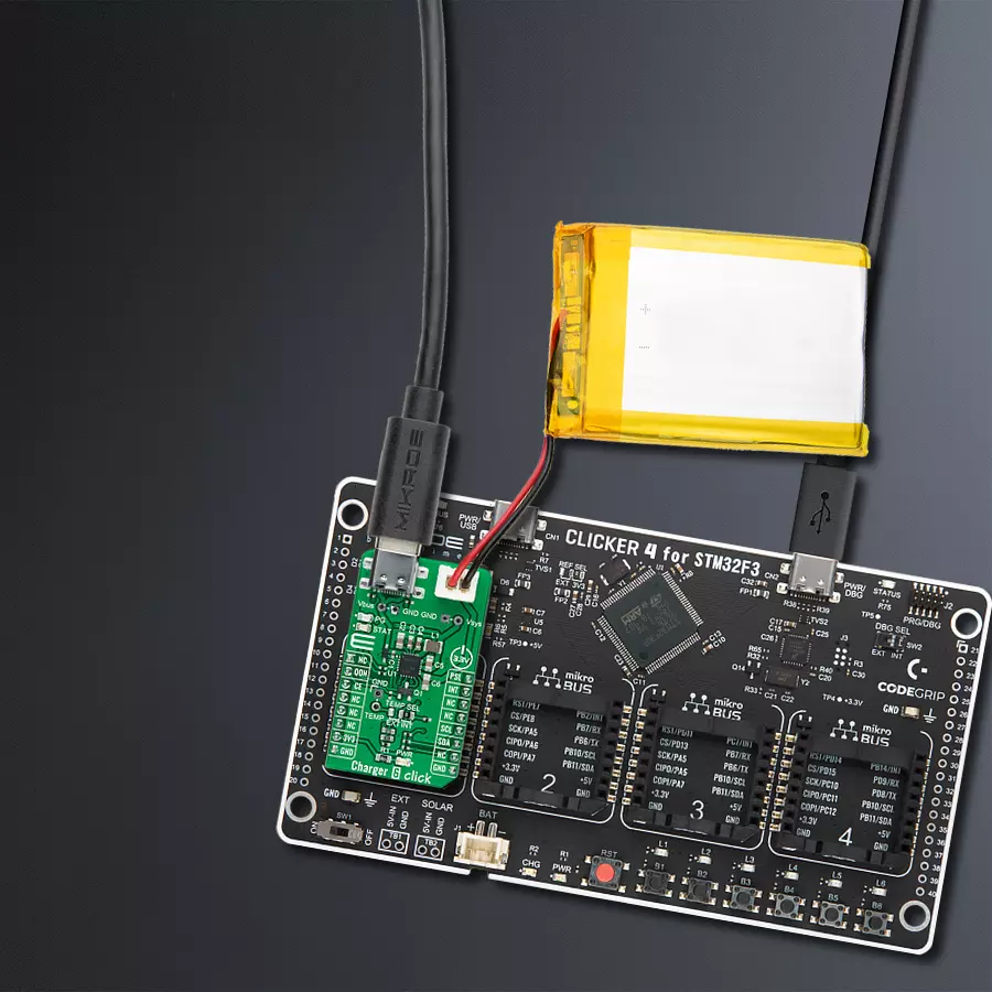
CLICKER 4 for STM32F302VCT6
Compiler
NECTO Studio
MCU
STM32F302VC
Take the first step towards a better charging solution for your device - choose our advanced battery charger today
A
A
Hardware Overview
How does it work?
Charger 6 Click is based on the BQ25601, a fast-charging solution for single-cell Li-Ion and Li-polymer batteries with high input voltage suitable for a wide range of smartphones, tablets, and portable devices from Texas Instruments. The low-impedance power path optimizes switch-mode operation efficiency, reduces battery charging time, and extends battery life during discharge. It is optimized for USB 5V voltage input, has a programmable current limiting based on the built-in USB interface, and allows an external power supply from 3.9 to 13.5V. The BQ25601 also meets USB On-the-Go (OTG) operation power rating specification by supplying 5.15 V on the VBUS line with a constant current limit of up to 1.2A. The device provides automatic power path selection on the SYS line from the VBUS input source, battery, or both. The power path management regulates the system slightly above the battery voltage but does not drop below the 3.5V minimum system voltage. With this feature, the system maintains operation even when the battery is completely removed.
When the input current limit or voltage limit is reached, the power path management automatically reduces the charge current to zero. As the system load increases, the power path discharges the battery until the system power requirement is met. Charger 6 Click communicates with MCU using the standard I2C 2-Wire interface and supports both Standard and Fast Mode with a transfer rate of 100 and 400kbit/s. The I2C serial interface with charging and system settings makes this Click board™ a truly flexible solution. Also, it uses several GPIO pins, one of which is an interrupt pin, the INT pin of the mikroBUS™ socket, used as a ‘fault’ indicator. This pin sets immediately notifies the host when a fault occurs. This Click board™ also uses two LED indicators, PG and STAT, as power good and charging status indicators. PG indicates a good input source if the input voltage is above the SLEEP mode threshold and the current limit is above 30mA, while STAT reports the charging status and any fault conditions. The CE pin routed to the CS pin on the mikroBUS™ socket enables the battery charging
process by setting this pin into a low logic state. PSEL pin routed to the PWM pin on the mikroBUS™ socket is used as a power source selection input and sets a 500mA input current limit by pulling this pin high; otherwise, set 2.4A input current limit by pulling this pin low. The BQ25601 also provides a QON pin, routed to the RST pin on the mikroBUS™ socket, for BATFET enable and reset control, to exit low-power mode or the whole system reset function. The charger provides a selectable temperature monitoring feature via a TEMP SEL jumper, where the user can choose between external or internal monitoring. A single thermistor input for the battery temperature monitor is provided for external mode. This Click board™ can only be operated with a 3.3V logic voltage level. The board must perform appropriate logic voltage level conversion before using MCUs with different logic levels. However, the Click board™ comes equipped with a library containing functions and an example code that can be used as a reference for further development.

Features overview
Development board
Clicker 4 for STM32F3 is a compact development board designed as a complete solution, you can use it to quickly build your own gadgets with unique functionalities. Featuring a STM32F302VCT6, four mikroBUS™ sockets for Click boards™ connectivity, power managment, and more, it represents a perfect solution for the rapid development of many different types of applications. At its core, there is a STM32F302VCT6 MCU, a powerful microcontroller by STMicroelectronics, based on the high-
performance Arm® Cortex®-M4 32-bit processor core operating at up to 168 MHz frequency. It provides sufficient processing power for the most demanding tasks, allowing Clicker 4 to adapt to any specific application requirements. Besides two 1x20 pin headers, four improved mikroBUS™ sockets represent the most distinctive connectivity feature, allowing access to a huge base of Click boards™, growing on a daily basis. Each section of Clicker 4 is clearly marked, offering an intuitive and clean interface. This makes working with the development
board much simpler and thus, faster. The usability of Clicker 4 doesn’t end with its ability to accelerate the prototyping and application development stages: it is designed as a complete solution which can be implemented directly into any project, with no additional hardware modifications required. Four mounting holes [4.2mm/0.165”] at all four corners allow simple installation by using mounting screws. For most applications, a nice stylish casing is all that is needed to turn the Clicker 4 development board into a fully functional, custom design.

Microcontroller Overview
MCU Card / MCU

Architecture
ARM Cortex-M4
MCU Memory (KB)
256
Silicon Vendor
STMicroelectronics
Pin count
100
RAM (Bytes)
40960
You complete me!
Accessories
Li-Polymer Battery is the ideal solution for devices that demand a dependable and long-lasting power supply while emphasizing mobility. Its compatibility with mikromedia boards ensures easy integration without additional modifications. With a voltage output of 3.7V, the battery meets the standard requirements of many electronic devices. Additionally, boasting a capacity of 2000mAh, it can store a substantial amount of energy, providing sustained power for extended periods. This feature minimizes the need for frequent recharging or replacement. Overall, the Li-Polymer Battery is a reliable and autonomous power source, ideally suited for devices requiring a stable and enduring energy solution. You can find a more extensive choice of Li-Polymer batteries in our offer.

Used MCU Pins
mikroBUS™ mapper
Take a closer look
Click board™ Schematic

Step by step
Project assembly

Start by selecting your development board and Click board™. Begin with the CLICKER 4 for STM32F302VCT6 as your development board.


Software Support
Library Description
This library contains API for Charger 6 Click driver.
Key functions:
charger6_cfg_setup- Config Object Initialization function.charger6_init- Initialization function.charger6_default_cfg- Click Default Configuration function.
Open Source
Code example
The complete application code and a ready-to-use project are available through the NECTO Studio Package Manager for direct installation in the NECTO Studio. The application code can also be found on the MIKROE GitHub account.
/*!
 * @file main.c
 * @brief Charger6 Click example
 *
 * # Description
 * This library contains API for the Charger 6 Click driver.
 * The library contains drivers to enable/disable battery charging,
 * set current limit, set system min voltage, set fast charge current,
 * set charge voltage, etc.
 *
 * The demo application is composed of two sections :
 *
 * ## Application Init
 * Initializes I2C driver and set default configuration:
 * input current limit set to 500 mA, system minimum voltage to 3500 mV,
 * fast charge current set to 360 mA, charge voltage to 4112 mV and
 * enable battery charging.
 *
 * ## Application Task
 * This example monitors the operation of the Charger 6 Click and all its charging states.
 * The user can observe information such as charging status, selected mode,
 * charging current value, and the momentary value of the supply voltage relative to the battery voltage.
 * Results are being sent to the Usart Terminal where you can track their changes.
 *
 * @author Nenad Filipovic
 *
 */

#include "board.h"
#include "log.h"
#include "charger6.h"

static charger6_t charger6;
static log_t logger;

charger6_status_t chg_status;
static uint16_t charge_current;

void display_chrg_status ( void ) {
    log_printf( &logger, " Charging   :" );
    switch ( chg_status.chrg_stat ) {
        case CHARGER6_R08_CHRG_STAT_NOT_CHARGING : {
            log_printf( &logger, " Not Charging\r\n" );
            break;
        }
        case CHARGER6_R08_CHRG_STAT_PRE_CHARGE : {
            log_printf( &logger, " Pre-charge\r\n" );
            break;
        }
        case CHARGER6_R08_CHRG_STAT_FAST_CHARGING : {
            log_printf( &logger, " Fast Charging\r\n" );
            charge_current = charger6_get_fast_charge_current( &charger6 );
            log_printf( &logger, " Chg Current: %u mA\r\n", charge_current );
            break;
        }
        case CHARGER6_R08_CHRG_STAT_CHARGE_TERMINATION : {
            log_printf( &logger, " Charge Termination\r\n" );
            break;
        }
        default : {
            log_printf( &logger, " Unknown\r\n" );
            break;
        }
    }
}

void display_power_good_status ( void ) {
    log_printf( &logger, " Power      :" );
    switch ( chg_status.pg_stat ) {
        case CHARGER6_R08_PG_STAT_POWER_NOT_GOOD : {
            log_printf( &logger, " Power Not Good\r\n" );
            break;
        }
        case CHARGER6_R08_PG_STAT_POWER_GOOD : {
            log_printf( &logger, " Power Good\r\n" );
            break;
        }
        default : {
            log_printf( &logger, " Unknown\r\n" );
            break;
        }
    }
}

void display_vsys_status ( void ) {
    log_printf( &logger, " Vsys       :" );
    switch ( chg_status.vsys_stat ) {
        case CHARGER6_R08_VSYS_STAT_NOT : {
            log_printf( &logger, " BAT > Vsys Min\r\n" );
            break;
        }
        case CHARGER6_R08_VSYS_STAT_VSYSM : {
            log_printf( &logger, " BAT < Vsys Min\r\n" );
            break;
        }
        default : {
            log_printf( &logger, " Unknown\r\n" );
            break;
        }
    }
}


void display_bat_status ( void ) {
    log_printf( &logger, " Battery    :" );
    switch ( chg_status.bat_fault ) {
        case CHARGER6_R09_BAT_FAULT_NORMAL : {
            log_printf( &logger, " Normal\r\n" );
            break;
        }
        case CHARGER6_R08_VSYS_STAT_VSYSM : {
            log_printf( &logger, " Overvoltage\r\n" );
            break;
        }
        default : {
            log_printf( &logger, " Unknown\r\n" );
            break;
        }
    }
}

void display_chrg_fault_status ( void ) {
    log_printf( &logger, " Chrg fault :" );
    switch ( chg_status.chrg_fault ) {
        case CHARGER6_R09_CHRG_FAULT_NORMAL : {
            log_printf( &logger, " Normal\r\n" );
            break;
        }
        case CHARGER6_R09_CHRG_FAULT_INPUT_FAULT : {
            log_printf( &logger, " Input fault\r\n" );
            break;
        }
        case CHARGER6_R09_CHRG_FAULT_THERMAL_SHUTDOWN : {
            log_printf( &logger, " Thermal shutdown\r\n" );
            break;
        }
        case CHARGER6_R09_CHRG_FAULT_CHG_SAFETY_TIMER_EXP : {
            log_printf( &logger, " Charge Safety Timer Expiration\r\n" );
            break;
        }
        default : {
            log_printf( &logger, " Unknown\r\n" );
            break;
        }
    }
}

void application_init ( void ) {
    log_cfg_t log_cfg;            /**< Logger config object. */
    charger6_cfg_t charger6_cfg;  /**< Click config object. */

    /**
     * Logger initialization.
     * Default baud rate: 115200
     * Default log level: LOG_LEVEL_DEBUG
     * @note If USB_UART_RX and USB_UART_TX
     * are defined as HAL_PIN_NC, you will
     * need to define them manually for log to work.
     * See @b LOG_MAP_USB_UART macro definition for detailed explanation.
     */
    LOG_MAP_USB_UART( log_cfg );
    log_init( &logger, &log_cfg );
    log_info( &logger, " Application Init " );

    // Click initialization.

    charger6_cfg_setup( &charger6_cfg );
    CHARGER6_MAP_MIKROBUS( charger6_cfg, MIKROBUS_1 );
    err_t init_flag = charger6_init( &charger6, &charger6_cfg );
    if ( init_flag == I2C_MASTER_ERROR ) {
        log_error( &logger, " Application Init Error. " );
        log_info( &logger, " Please, run program again... " );

        for ( ; ; );
    }

    charger6_default_cfg ( &charger6 );
    log_info( &logger, " Application Task " );
    Delay_ms ( 1000 );

    log_printf( &logger, "-------------------------------\r\n" );
    log_printf( &logger, " Set Current Limit   :  500 mA \r\n" );
    charger6_set_input_current_limit( &charger6, 500 );
    Delay_ms ( 100 );

    log_printf( &logger, " Set Sys Min Voltage : 3500 mV \r\n" );
    charger6_set_system_minimum_voltage( &charger6, 3500 );
    Delay_ms ( 100 );

    log_printf( &logger, " Set Fast Chg Current:  360 mA \r\n" );
    charger6_set_fast_charge_current( &charger6, 360 );
    Delay_ms ( 100 );

    log_printf( &logger, " Set Charge Voltage  : 4112 mV \r\n" );
    charger6_set_charge_voltage( &charger6, 4112 );
    Delay_ms ( 100 );

    log_printf( &logger, " >> Enable Battery Charging << \r\n" );
    charger6_enable_battery_charging( &charger6 );
    Delay_ms ( 1000 );

    log_printf( &logger, "-------------------------------\r\n" );
    log_printf( &logger, "       >>>   Status   <<<      \r\n" );
    log_printf( &logger, "-------------------------------\r\n" );
}

void application_task ( void ) {
    charger6_get_status( &charger6, &chg_status );
    Delay_ms ( 100 );

    display_power_good_status( );
    Delay_ms ( 100 );

    display_chrg_status( );
    Delay_ms ( 100 );

    display_bat_status( );
    Delay_ms ( 100 );

    display_chrg_fault_status( );
    Delay_ms ( 100 );

    display_vsys_status( );
    log_printf( &logger, "-------------------------------\r\n" );
    Delay_ms ( 1000 );
    Delay_ms ( 1000 );
}

int main ( void )
{
    /* Do not remove this line or clock might not be set correctly. */
    #ifdef PREINIT_SUPPORTED
    preinit();
    #endif

    application_init( );

    for ( ; ; )
    {
        application_task( );
    }

    return 0;
}

// ------------------------------------------------------------------------ END
Additional Support
Resources
Category:Battery charger


