Unleash the power of LEDs with MCP1664 and PIC32MZ2048EFH100
Illuminate and enchant
Published Sep 04, 2023
Click board™
MCP1664 Click
Dev. board
Flip&Click PIC32MZ
Compiler
NECTO Studio
MCU
PIC32MZ2048EFH100
Illuminate every space confidently using our white LED driver solution, ensuring vibrant, energy-efficient lighting that captivates and enhances any environment
A
A
Hardware Overview
How does it work?
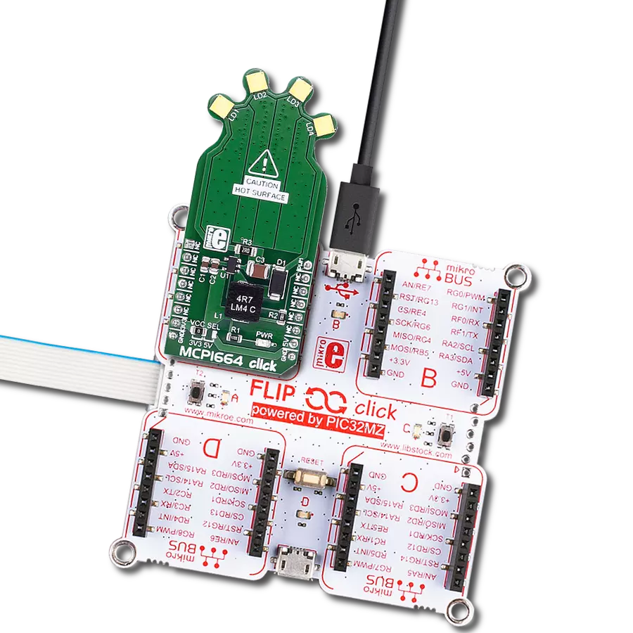
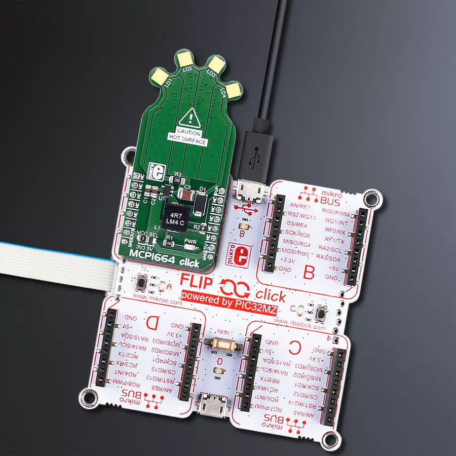
MCP1664 Click is based on four high-power white LEDs. It carries the MCP1664, a high-voltage step-up LED driver from Microchip. MCP1664 click is designed to run on either a 3.3V or 5V power supply. It communicates with the target board microcontroller over the PWM pin on the mikroBUS™ line. The click has a power and PWM input to set the light intensity at the desired level. The MCP1664 is a compact, space-efficient, fixed-frequency, non-synchronous step-up converter
optimized to drive multiple strings of LEDs with constant current powered from two and three-cell alkaline or NiMH/NiCd as well as from one-cell Li-Ion or Li-Polymer batteries. The MCP1664 features open load protection (OLP), which turns off the operation when the LED string is accidentally disconnected or the feedback pin is short-circuited to GND. While in Shutdown mode (EN = GND), the device stops switching and consumes 40 nA, typical of the input current. This Click
board™ can operate with either 3.3V or 5V logic voltage levels selected via the VCC SEL jumper. This way, both 3.3V and 5V capable MCUs can use the communication lines properly. Also, this Click board™ comes equipped with a library containing easy-to-use functions and an example code that can be used as a reference for further development.


Features overview
Development board
Flip&Click PIC32MZ is a compact development board designed as a complete solution that brings the flexibility of add-on Click boards™ to your favorite microcontroller, making it a perfect starter kit for implementing your ideas. It comes with an onboard 32-bit PIC32MZ microcontroller, the PIC32MZ2048EFH100 from Microchip, four mikroBUS™ sockets for Click board™ connectivity, two USB connectors, LED indicators, buttons, debugger/programmer connectors, and two headers compatible with Arduino-UNO pinout. Thanks to innovative manufacturing technology,
it allows you to build gadgets with unique functionalities and features quickly. Each part of the Flip&Click PIC32MZ development kit contains the components necessary for the most efficient operation of the same board. In addition, there is the possibility of choosing the Flip&Click PIC32MZ programming method, using the chipKIT bootloader (Arduino-style development environment) or our USB HID bootloader using mikroC, mikroBasic, and mikroPascal for PIC32. This kit includes a clean and regulated power supply block through the USB Type-C (USB-C) connector. All communication
methods that mikroBUS™ itself supports are on this board, including the well-established mikroBUS™ socket, user-configurable buttons, and LED indicators. Flip&Click PIC32MZ development kit allows you to create a new application in minutes. Natively supported by Mikroe software tools, it covers many aspects of prototyping thanks to a considerable number of different Click boards™ (over a thousand boards), the number of which is growing every day.

Microcontroller Overview
MCU Card / MCU

Architecture
PIC32
MCU Memory (KB)
2048
Silicon Vendor
Microchip
Pin count
100
RAM (Bytes)
524288
Used MCU Pins
mikroBUS™ mapper
Take a closer look
Click board™ Schematic

Step by step
Project assembly

Start by selecting your development board and Click board™. Begin with the Flip&Click PIC32MZ as your development board.


Software Support
Library Description
This library contains API for MCP1664 Click driver.
Key functions:
mcp1664_pwm_start- Start PWM modulemcp1664_pwm_stop- Stop PWM module
Open Source
Code example
The complete application code and a ready-to-use project are available through the NECTO Studio Package Manager for direct installation in the NECTO Studio. The application code can also be found on the MIKROE GitHub account.
/*!
 * \file
 * \brief Mcp1664 Click example
 *
 * # Description
 * This application turn on and turn off white LEDs.
 *
 * The demo application is composed of two sections :
 *
 * ## Application Init
 * Enables GPIO and PWM, sets the frequency and duty cycle and enables PWM.
 *
 * ## Application Task
 * This is a example which demonstrates the use of MCP1664 Click board.
 * It shows how to enable the device and gradualy increase the duty cycle.
 *
 * \author MikroE Team
 *
 */
// ------------------------------------------------------------------- INCLUDES

#include "board.h"
#include "log.h"
#include "mcp1664.h"

// ------------------------------------------------------------------ VARIABLES

static mcp1664_t mcp1664;
static log_t logger;

static float duty_cycle = 0.5;

// ------------------------------------------------------ APPLICATION FUNCTIONS

void application_init ( void )
{
    log_cfg_t log_cfg;
    mcp1664_cfg_t cfg;

    /**
     * Logger initialization.
     * Default baud rate: 115200
     * Default log level: LOG_LEVEL_DEBUG
     * @note If USB_UART_RX and USB_UART_TX
     * are defined as HAL_PIN_NC, you will
     * need to define them manually for log to work.
     * See @b LOG_MAP_USB_UART macro definition for detailed explanation.
     */
    LOG_MAP_USB_UART( log_cfg );
    log_init( &logger, &log_cfg );
    log_info( &logger, "---- Application Init ----" );

    //  Click initialization.

    mcp1664_cfg_setup( &cfg );
    MCP1664_MAP_MIKROBUS( cfg, MIKROBUS_1 );
    mcp1664_init( &mcp1664, &cfg );

    mcp1664_set_duty_cycle( &mcp1664, duty_cycle );
    mcp1664_pwm_start( &mcp1664 );
    Delay_ms ( 1000 );
    log_printf( &logger, "------------------ \r\n" );
    log_printf( &logger, "  MCP1664  Click   \r\n" );
    log_printf( &logger, "------------------ \r\n" );
    Delay_ms ( 100 );
}

void application_task ( void )
{
    //  Task implementation.

    if ( duty_cycle > 1 )
    {
        duty_cycle = 0.1;
    }

    mcp1664_set_duty_cycle ( &mcp1664, duty_cycle );
    duty_cycle += 0.1;
    Delay_100ms();

    log_printf( &logger,  "  Duty cycle is : %d  \r\n", duty_cycle );
}

int main ( void )
{
    /* Do not remove this line or clock might not be set correctly. */
    #ifdef PREINIT_SUPPORTED
    preinit();
    #endif

    application_init( );

    for ( ; ; )
    {
        application_task( );
    }

    return 0;
}


// ------------------------------------------------------------------------ END
Additional Support
Resources
Category:LED Drivers


