Detect the presence or absence of objects nearby with the RPR-0720 and PIC32MZ2048EFH100
Digital optical proximity detection sensing solution

Published Jul 04, 2024
Click board™
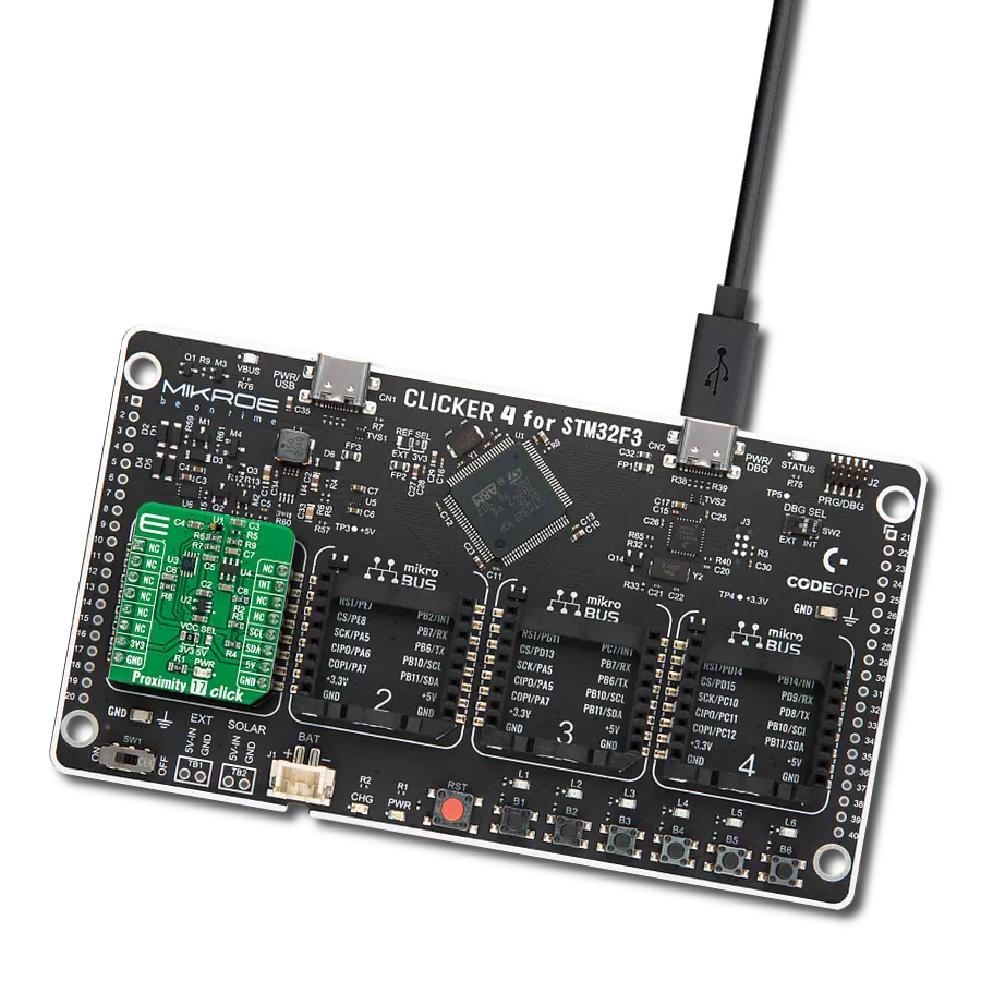
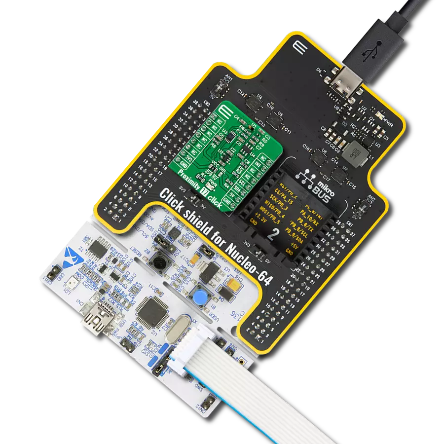
Proximity 19 Click
Dev. board
Flip&Click PIC32MZ
Compiler
NECTO Studio
MCU
PIC32MZ2048EFH100
Trigger actions in smart home or industrial automation applications based on hand movements or object proximity
A
A
Hardware Overview
How does it work?
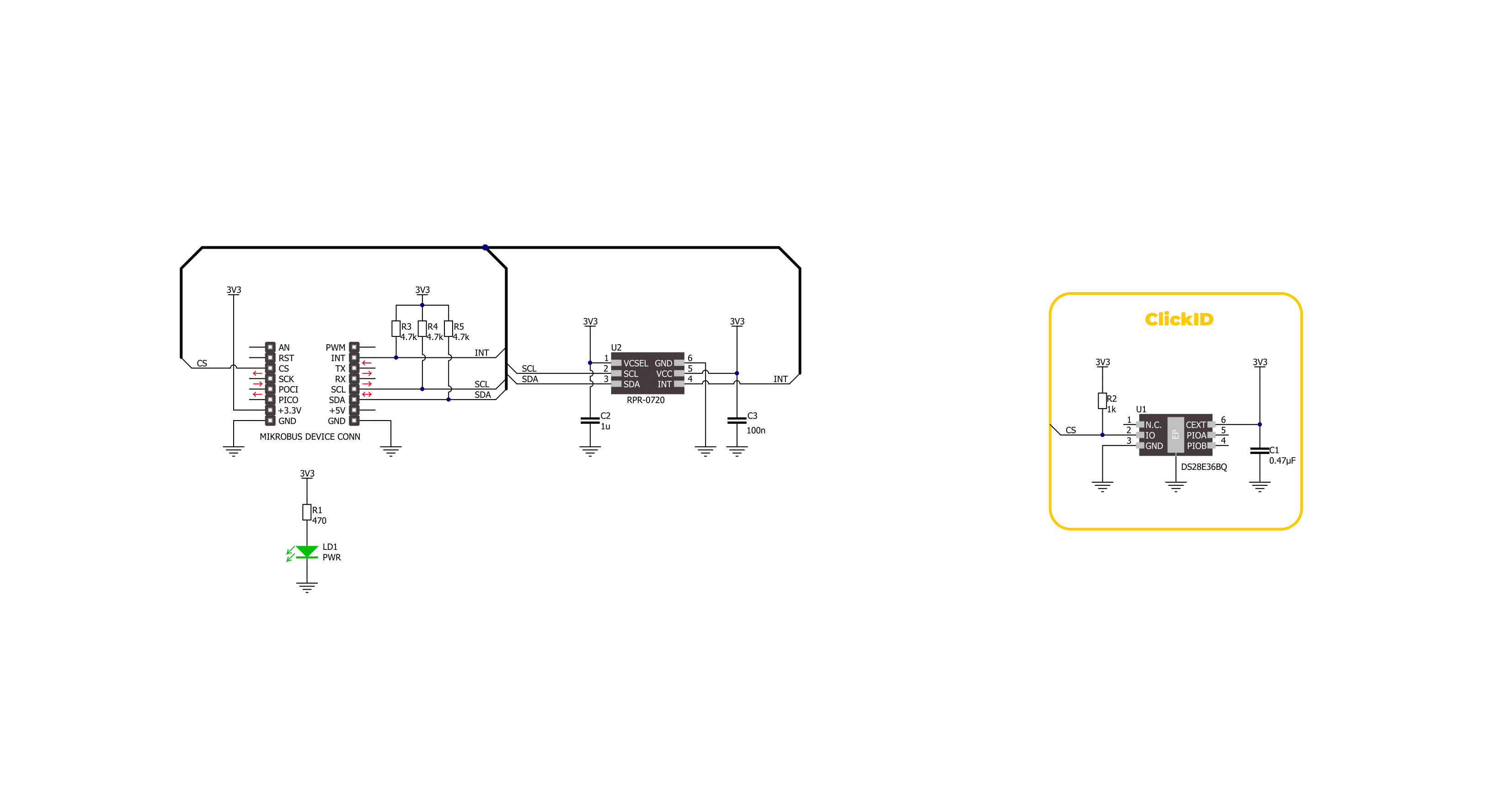
Proximity 19 Click is based on the RPR-0720, a miniature digital optical proximity sensor from ROHM Semiconductor that integrates an infrared VCSEL (IrVCSEL) and an IC with an I2C interface in a tiny package. This IC includes a built-in infrared receiver and VCSEL driver, enabling the sensor to detect human presence or objects by reflecting IrVCSEL light. The detection range of the proximity sensor is adjustable from approximately 1 to 15mm. Additionally, it is equipped with an
ambient light canceling function, making it ideal for use in wearable and AR/VR devices, among other applications. Proximity 19 Click uses a standard 2-wire I2C interface to communicate with the host MCU, supporting Standard mode with up to 400kHz of frequency clock. The I2C interface and registers allow for controlling various sensor functions, such as operating mode control, interrupt system management for interrupt signals available on INT pin, and adjusting offset and threshold values for
proximity sensor data. This flexibility ensures precise and customizable operations tailored to specific application needs. This Click board™ can be operated only with a 3.3V logic voltage level. The board must perform appropriate logic voltage level conversion before using MCUs with different logic levels. Also, it comes equipped with a library containing functions and an example code that can be used as a reference for further development.

Features overview
Development board
Flip&Click PIC32MZ is a compact development board designed as a complete solution that brings the flexibility of add-on Click boards™ to your favorite microcontroller, making it a perfect starter kit for implementing your ideas. It comes with an onboard 32-bit PIC32MZ microcontroller, the PIC32MZ2048EFH100 from Microchip, four mikroBUS™ sockets for Click board™ connectivity, two USB connectors, LED indicators, buttons, debugger/programmer connectors, and two headers compatible with Arduino-UNO pinout. Thanks to innovative manufacturing technology,
it allows you to build gadgets with unique functionalities and features quickly. Each part of the Flip&Click PIC32MZ development kit contains the components necessary for the most efficient operation of the same board. In addition, there is the possibility of choosing the Flip&Click PIC32MZ programming method, using the chipKIT bootloader (Arduino-style development environment) or our USB HID bootloader using mikroC, mikroBasic, and mikroPascal for PIC32. This kit includes a clean and regulated power supply block through the USB Type-C (USB-C) connector. All communication
methods that mikroBUS™ itself supports are on this board, including the well-established mikroBUS™ socket, user-configurable buttons, and LED indicators. Flip&Click PIC32MZ development kit allows you to create a new application in minutes. Natively supported by Mikroe software tools, it covers many aspects of prototyping thanks to a considerable number of different Click boards™ (over a thousand boards), the number of which is growing every day.

Microcontroller Overview
MCU Card / MCU

Architecture
PIC32
MCU Memory (KB)
2048
Silicon Vendor
Microchip
Pin count
100
RAM (Bytes)
524288
Used MCU Pins
mikroBUS™ mapper
Take a closer look
Click board™ Schematic
Step by step
Project assembly

Start by selecting your development board and Click board™. Begin with the Flip&Click PIC32MZ as your development board.


Track your results in real time
Application Output
1. Application Output - In Debug mode, the 'Application Output' window enables real-time data monitoring, offering direct insight into execution results. Ensure proper data display by configuring the environment correctly using the provided tutorial.

2. UART Terminal - Use the UART Terminal to monitor data transmission via a USB to UART converter, allowing direct communication between the Click board™ and your development system. Configure the baud rate and other serial settings according to your project's requirements to ensure proper functionality. For step-by-step setup instructions, refer to the provided tutorial.

3. Plot Output - The Plot feature offers a powerful way to visualize real-time sensor data, enabling trend analysis, debugging, and comparison of multiple data points. To set it up correctly, follow the provided tutorial, which includes a step-by-step example of using the Plot feature to display Click board™ readings. To use the Plot feature in your code, use the function: plot(*insert_graph_name*, variable_name);. This is a general format, and it is up to the user to replace 'insert_graph_name' with the actual graph name and 'variable_name' with the parameter to be displayed.

Software Support
Library Description
This library contains API for Proximity 19 Click driver.
Key functions:
proximity19_get_distance- This function reads the distance measured by the sensor in millimeters by using the I2C serial interface.proximity19_set_ps_gain- This function adjusts the gain of the sensor's sensitivity to light reception.proximity19_set_period- This function sets the desired data measurement period value.
Open Source
Code example
The complete application code and a ready-to-use project are available through the NECTO Studio Package Manager for direct installation in the NECTO Studio. The application code can also be found on the MIKROE GitHub account.
/*!
 * @file main.c
 * @brief Proximity 19 Click example
 *
 * # Description
 * This example demonstrates the use of the Proximity 19 Click board
 * by measuring and displaying the distance data.
 *
 * The demo application is composed of two sections :
 *
 * ## Application Init
 * Initialization of I2C module and log UART.
 * After the driver init, the app executes a default configuration.
 *
 * ## Application Task
 * The demo app measures the distance between the sensor and the object in millimeters
 * and displays the result approximately every 100 milliseconds.
 * Results are being sent to the UART Terminal, where you can track their changes.
 *
 * @author Nenad Filipovic
 *
 */

#include "board.h"
#include "log.h"
#include "proximity19.h"

static proximity19_t proximity19;
static log_t logger;

void application_init ( void )
{
    log_cfg_t log_cfg;  /**< Logger config object. */
    proximity19_cfg_t proximity19_cfg;  /**< Click config object. */

    /**
     * Logger initialization.
     * Default baud rate: 115200
     * Default log level: LOG_LEVEL_DEBUG
     * @note If USB_UART_RX and USB_UART_TX
     * are defined as HAL_PIN_NC, you will
     * need to define them manually for log to work.
     * See @b LOG_MAP_USB_UART macro definition for detailed explanation.
     */
    LOG_MAP_USB_UART( log_cfg );
    log_init( &logger, &log_cfg );
    log_info( &logger, " Application Init " );

    // Click initialization.
    proximity19_cfg_setup( &proximity19_cfg );
    PROXIMITY19_MAP_MIKROBUS( proximity19_cfg, MIKROBUS_1 );
    if ( I2C_MASTER_ERROR == proximity19_init( &proximity19, &proximity19_cfg ) )
    {
        log_error( &logger, " Communication init." );
        for ( ; ; );
    }

    if ( PROXIMITY19_ERROR == proximity19_default_cfg ( &proximity19 ) )
    {
        log_error( &logger, " Default configuration." );
        for ( ; ; );
    }

    log_info( &logger, " Application Task " );
}

void application_task ( void )
{
    float distance = 0;
    if ( PROXIMITY19_OK == proximity19_get_distance( &proximity19, &distance ) )
    {
        log_printf( &logger, " Distance: %.2f [mm] \r\n\n", distance );
    }
    Delay_ms ( 100 );
}

int main ( void )
{
    /* Do not remove this line or clock might not be set correctly. */
    #ifdef PREINIT_SUPPORTED
    preinit();
    #endif

    application_init( );

    for ( ; ; )
    {
        application_task( );
    }

    return 0;
}

// ------------------------------------------------------------------------ END