Make interactions more intuitive with CAP1293 and STM32F405RG
Start with just a touch

Published Aug 07, 2023
Click board™
TouchKey 4 click
Dev. board
SparkFun MicroMod mikroBUS Carrier Board
Compiler
NECTO Studio
MCU
STM32F405RG
Join the movement and create interfaces that come alive with touch functions
A
A
Hardware Overview
How does it work?
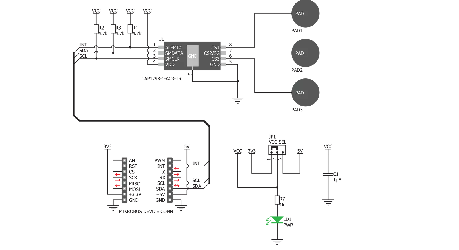
TouchKey 4 Click is based on the CAP1293, 3-channel capacitive touch sensor with proximity detection from Microchip. This IC has three independently configurable capacitive touch channels with the auto-calibration function. It uses the I2C protocol for the communication, with the I2C bus pins routed to the respective mikroBUS™ pins: SMCLK is the I2C clock pin, routed to the SCK pin of the mikroBUS™ and the SMDATA is the I2C data pin, routed to the SDA pin of the mikroBUS™. Additionally, an #ALERT pin is routed to the mikroBUS™ INT pin, which triggers interrupts on the host MCU. The board has three PCB pads used to sense touch or proximity events. These pads are the only elements on the top side of the board, allowing the installation of the protective acrylic glass layer. The capacitive sensor channels feature a programmable sensitivity threshold and an automatic recalibration to compensate for environmental changes. The device can work in several power modes, with separate input settings for the Active and Standby modes. The recalibration procedure can be triggered either automatically or on-demand, and it is used to set the base register value for the “not touched” state of the input channel. The CAP1293 IC also integrates sections that provide efficient interference protection. The EMI and RFI detection
sections protect by discarding the corrupted bytes if the detected noise threshold is exceeded. Also, false input readings, such as the negative values and “stuck button” events, are handled by the internal algorithms, which will set the respective bits to indicate the problem, and can be set to trigger a recalibration procedure. In general, the device always reverts to a power-saving mode when idling. If the programmed cycling time through all the enabled channels is long enough, sampling all the enabled channels will be finished before the cycle ends. When this happens, the device will revert to a power-saving mode, waiting for another cycle to begin. If there is insufficient time to sample all the channels, the device will not revert to a power-saving mode. This will affect the overall power consumption. Multiple touch pattern detection (MTPD) sets the pattern to generate a touch event. This pattern may consist of multiple specific sensors touched at once, a minimal number of touched sensors, or when their noise flag bit is set in the status register. This function can be used to detect a closed lid or similar event. The interrupt engine differentiates between the simple touch and touch and holds events. The interrupt can be generated once when a pad touch is detected/released or repeatedly generated while the pad is touched.
A special case of touch detection is the Power Button mode. This mode requires the button to be pressed for a programmed interval before an interrupt is generated. This allows a simple Power Button functionality to be implemented in any application. The interrupt can be generated for various other events, such as the failure to calibrate and similar auxiliary events. The press and hold mode is useful for developing volume control applications. The programmable interval timer is started after the first touch event on a specific channel. The interrupt is generated in the programmed intervals if no release event is detected after the timer expires. This can be used to implement volume up/down buttons, light-dimming buttons, and similar applications. Any interrupt event will drive the #ALERT pin to a LOW logic state. This pin is routed to the mikroBUS™ INT pin and is used to trigger an interrupt event on the host MCU. More information about the registers and their functions can be found in the CAP1293 IC datasheet. However, the provided click library offers a function for easy and simple control of the Touch Key 4 Click. The provided application example demonstrates their functionality and can be used as a reference for custom projects.


Features overview
Development board
SparkFun MicroMod mikroBUS Carrier board takes advantage of the MicroMod, Qwiic, and mikroBUS™ ecosystems making it easy to prototype with each combined rapidly. The MicroMod M.2 socket and mikroBUS™ 8-pin header allow users to experiment with any processor board in the MicroMod ecosystem and any Click board™ in the mikroBUS™ ecosystem,
respectively. This board also features two Qwiic connectors to seamlessly integrate hundreds of Qwiic sensors and accessories into your project. The mikroBUS™ socket comprises a pair of 8-pin female headers with a standardized pin configuration. The pins consist of three groups of communications pins (SPI, UART, and I2C), six additional pins (PWM, Interrupt, Analog input,
Reset, and Chip select), and two power groups (3.3V and 5V). While a modern USB-C connector makes programming easy, the Carrier Board is also equipped with an MCP73831 single-cell Lithium-Ion/Lithium-Polymer charge IC so you can charge an attached single-cell Li-Po battery. The charge IC receives power from the USB connection and can source up to 450mA to charge an attached battery.

Microcontroller Overview
MCU Card / MCU
Architecture
ARM Cortex-M4
MCU Memory (KB)
1024
Silicon Vendor
STMicroelectronics
Pin count
64
RAM (Bytes)
196608
Used MCU Pins
mikroBUS™ mapper
Take a closer look
Click board™ Schematic
Step by step
Project assembly

Start by selecting your development board and Click board™. Begin with the SparkFun MicroMod mikroBUS Carrier Board as your development board.


Track your results in real time
Application Output
1. Application Output - In Debug mode, the 'Application Output' window enables real-time data monitoring, offering direct insight into execution results. Ensure proper data display by configuring the environment correctly using the provided tutorial.

2. UART Terminal - Use the UART Terminal to monitor data transmission via a USB to UART converter, allowing direct communication between the Click board™ and your development system. Configure the baud rate and other serial settings according to your project's requirements to ensure proper functionality. For step-by-step setup instructions, refer to the provided tutorial.

3. Plot Output - The Plot feature offers a powerful way to visualize real-time sensor data, enabling trend analysis, debugging, and comparison of multiple data points. To set it up correctly, follow the provided tutorial, which includes a step-by-step example of using the Plot feature to display Click board™ readings. To use the Plot feature in your code, use the function: plot(*insert_graph_name*, variable_name);. This is a general format, and it is up to the user to replace 'insert_graph_name' with the actual graph name and 'variable_name' with the parameter to be displayed.

Software Support
Library Description
This library contains API for TouchKey 4 Click driver.
Key functions:
touchkey4_detect_touch- This function detects touch on sensor inputs and checks is touch detected or releasedtouchkey4_set_active_mode- This function puts device in Active mode and enables desired inputs in Active modetouchkey4_set_standby_mode- This function puts device in Standby mode and enables desired inputs in Standby mode.
Open Source
Code example
The complete application code and a ready-to-use project are available through the NECTO Studio Package Manager for direct installation in the NECTO Studio. The application code can also be found on the MIKROE GitHub account.
/*!
 * \file
 * \brief TouchKey4 Click example
 *
 * # Description
 * This demo performs touch & release detection Click functionality.
 *
 * The demo application is composed of two sections :
 *
 * ## Application Init
 * Device and driver initialization.
 *
 * ## Application Task
 * Calls function to check touch detection (is interrupt occured) and shows message on
 * USB UART if touch is detected or if touch is released on enabled inputs.
 *
 * *note:*
 * <pre>
 * TouchKey 4 is configured to work in Combo mode (Active and Standby mode). Input 1 is
 * enabled in Active mode, input 3 is enabled in Standby mode, and input 2 is enabled to
 * work in both modes. In this example the interrupt will be generated when touch is
 * detected and when touch is released.
 * Standby mode should be used when fewer sensor inputs are enabled, and when
 * they are programmed to have more sensitivity.
 * Sometimes it is neccessary to cycle the board power supply if Click doesn't work.
 * </pre>
 * \author MikroE Team
 *
 */
// ------------------------------------------------------------------- INCLUDES

#include "board.h"
#include "log.h"
#include "touchkey4.h"

// ------------------------------------------------------------------ VARIABLES

static touchkey4_t touchkey4;
static log_t logger;

static uint8_t sensor_results[ 3 ];
static uint8_t cnt;

// ------------------------------------------------------ APPLICATION FUNCTIONS

void application_init ( void )
{
    log_cfg_t log_cfg;
    touchkey4_cfg_t cfg;

    /**
     * Logger initialization.
     * Default baud rate: 115200
     * Default log level: LOG_LEVEL_DEBUG
     * @note If USB_UART_RX and USB_UART_TX
     * are defined as HAL_PIN_NC, you will
     * need to define them manually for log to work.
     * See @b LOG_MAP_USB_UART macro definition for detailed explanation.
     */
    LOG_MAP_USB_UART( log_cfg );
    log_init( &logger, &log_cfg );
    log_info( &logger, "---- Application Init ----" );

    //  Click initialization.

    touchkey4_cfg_setup( &cfg );
    TOUCHKEY4_MAP_MIKROBUS( cfg, MIKROBUS_1 );
    touchkey4_init( &touchkey4, &cfg );

    Delay_ms ( 1000 );

    touchkey4_default_cfg( &touchkey4 );
    log_info( &logger, "---- Configured and ready ----" );
}

void application_task ( void )
{
    touchkey4_detect_touch( &touchkey4, sensor_results );
    for ( cnt = 0; cnt < 3; cnt++ )
    {
        if ( sensor_results[ cnt ] == 1 )
        {
            if ( cnt == 0 )
            {
                log_info( &logger, "Input 1 is touched\r\n" );
            }
            else if ( cnt == 1 )
            {
                log_info( &logger, "Input 2 is touched\r\n" );
            }
            else
            {
                log_info( &logger, "Input 3 is touched\r\n" );
            }
        }
        else if ( sensor_results[ cnt ] == 2 )
        {
            if ( cnt == 0 )
            {
                log_info( &logger, "Input 1 is released\r\n" );
            }
            else if ( cnt == 1 )
            {
                log_info( &logger, "Input 2 is released\r\n" );
            }
            else
            {
                log_info( &logger, "Input 3 is released\r\n" );
            }
        }
    }
    Delay_ms ( 300 );
}


int main ( void )
{
    /* Do not remove this line or clock might not be set correctly. */
    #ifdef PREINIT_SUPPORTED
    preinit();
    #endif

    application_init( );

    for ( ; ; )
    {
        application_task( );
    }

    return 0;
}


// ------------------------------------------------------------------------ END
Additional Support
Resources
Category:Capacitive


