Control the direction of brushed DC motors with DRV8262 and PIC32MZ2048EFM100
H-Bridge motor driver with current sense output

Published Jan 03, 2024
Click board™
H-Bridge 16 Click
Dev. board
Curiosity PIC32 MZ EF
Compiler
NECTO Studio
MCU
PIC32MZ2048EFM100
Manage the movement of brushed DC motors in various devices like robots, medical equipment, and automated systems
A
A
Hardware Overview
How does it work?
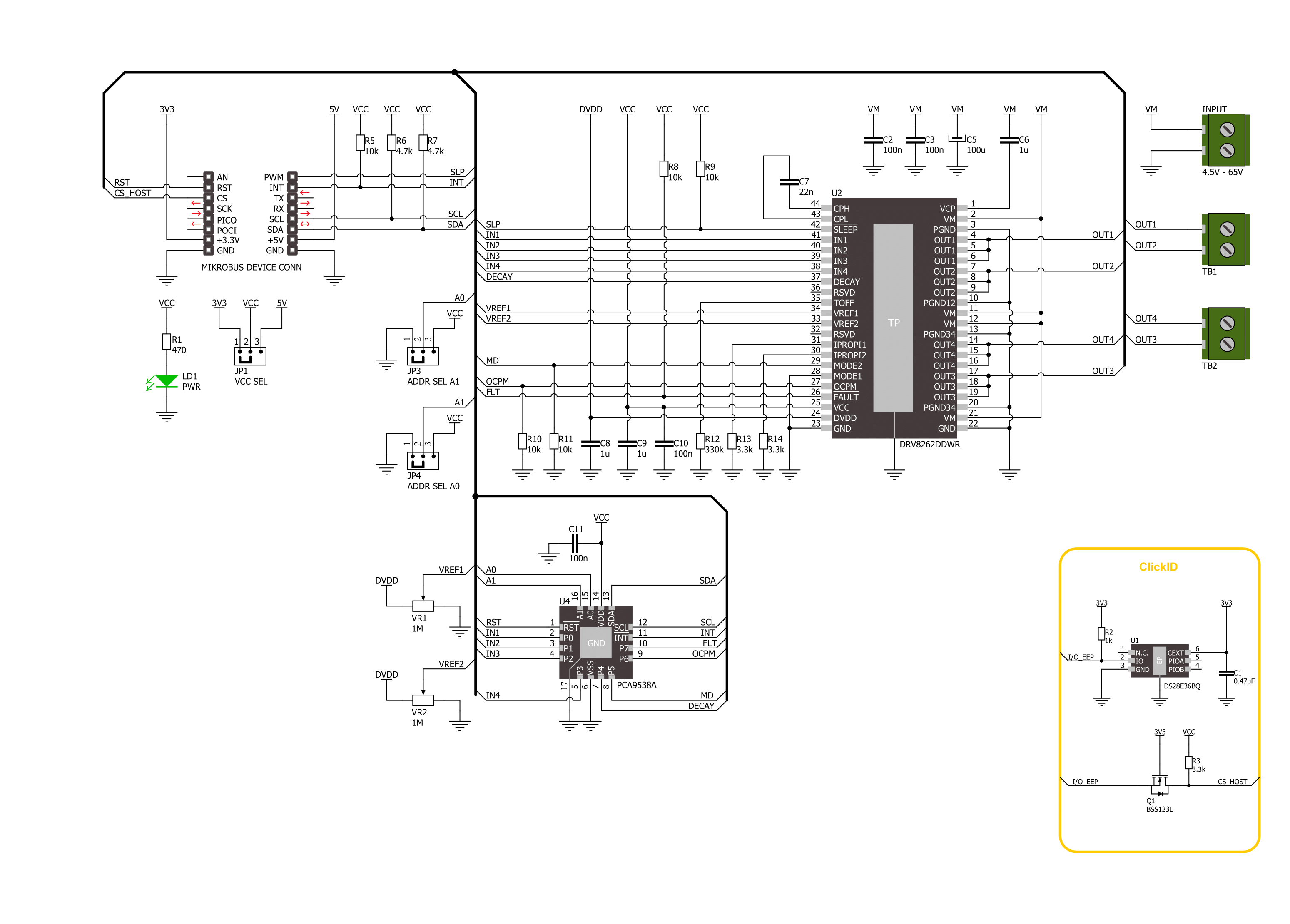
H-Bridge 16 Click is based on the DRV8262, a dual H-Bridge motor driver from Texas Instruments. It has a high output current capability and supports up to 8A peak current as a dual H-Bridge driver. You can configure the interface of operation between PH/EN and PWM. The PH/EN mode allows the H-Bridge to be controlled with a speed and direction type of interface. The PWM interface allows the H-Bridge outputs to become Hi-Z. There are two potentiometers (REF2 and REF1), which are reference voltage inputs for bridges 2 and 1. They are used to set the current limit for bridges. The integrated sensing uses a current mirror to limit the output current. The H-Bridge 16 Click uses
the PCA9538A, a low-voltage 8-bit I/O port, to control the IO pins of the motor driver. Over this I/PO port, you can set all four PWM inputs for both bridges. The Decay mode can be set between the slow decay for brake or high-side re-circulation and smart tune dynamic Decay mode. By setting the logic states on Mode2 of the motor driver, you can choose between the phase/enable and PWM interfaces. You can also determine the fault recovery method between the latch-off and auto-recovery. Finally, using the PCA9538A, you can monitor the fault indication of the motor driver. H-Bridge 16 Click uses a standard 2-wire I2C interface of the PCA9538A to allow the host MCU
to control the motor driver. You can reset the PCA9538A over the RST pin and read the interrupts of the motor driver through the I/O port over the INT pin. The I2C address can be selected over the ADDR SEL jumper. The host MCU can control the sleep mode of the motor driver directly over the SLP pin. This Click board™ can operate with either 3.3V or 5V logic voltage levels selected via the VCC SEL jumper. This way, both 3.3V and 5V capable MCUs can use the communication lines properly. Also, this Click board™ comes equipped with a library containing easy-to-use functions and an example code that can be used as a reference for further development.

Features overview
Development board
Curiosity PIC32 MZ EF development board is a fully integrated 32-bit development platform featuring the high-performance PIC32MZ EF Series (PIC32MZ2048EFM) that has a 2MB Flash, 512KB RAM, integrated FPU, Crypto accelerator, and excellent connectivity options. It includes an integrated programmer and debugger, requiring no additional hardware. Users can expand
functionality through MIKROE mikroBUS™ Click™ adapter boards, add Ethernet connectivity with the Microchip PHY daughter board, add WiFi connectivity capability using the Microchip expansions boards, and add audio input and output capability with Microchip audio daughter boards. These boards are fully integrated into PIC32’s powerful software framework, MPLAB Harmony,
which provides a flexible and modular interface to application development a rich set of inter-operable software stacks (TCP-IP, USB), and easy-to-use features. The Curiosity PIC32 MZ EF development board offers expansion capabilities making it an excellent choice for a rapid prototyping board in Connectivity, IOT, and general-purpose applications.

Microcontroller Overview
MCU Card / MCU

Architecture
PIC32
MCU Memory (KB)
2048
Silicon Vendor
Microchip
Pin count
100
RAM (Bytes)
524288
You complete me!
Accessories
DC Gear Motor - 430RPM (3-6V) represents an all-in-one combination of a motor and gearbox, where the addition of gear leads to a reduction of motor speed while increasing the torque output. This gear motor has a spur gearbox, making it a highly reliable solution for applications with lower torque and speed requirements. The most critical parameters for gear motors are speed, torque, and efficiency, which are, in this case, 520RPM with no load and 430RPM at maximum efficiency, alongside a current of 60mA and a torque of 50g.cm. Rated for a 3-6V operational voltage range and clockwise/counterclockwise rotation direction, this motor represents an excellent solution for many functions initially performed by brushed DC motors in robotics, medical equipment, electric door locks, and much more.

Used MCU Pins
mikroBUS™ mapper
Take a closer look
Click board™ Schematic
Step by step
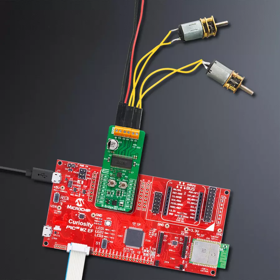
Project assembly

Start by selecting your development board and Click board™. Begin with the Curiosity PIC32 MZ EF as your development board.


Software Support
Library Description
This library contains API for H-Bridge 16 Click driver.
Key functions:
hbridge16_set_pins- H-Bridge 16 set pins function.hbridge16_set_mode- H-Bridge 16 set mode function.hbridge16_set_out_state- H-Bridge 16 set output function.
Open Source
Code example
The complete application code and a ready-to-use project are available through the NECTO Studio Package Manager for direct installation in the NECTO Studio. The application code can also be found on the MIKROE GitHub account.
/*!
 * @file main.c
 * @brief H-Bridge 16 Click example
 *
 * # Description
 * This example demonstrates the use of the H-Bridge 16 Click board by
 * driving the motor in both directions with braking and freewheeling.
 *
 * The demo application is composed of two sections :
 *
 * ## Application Init
 * Initializes the driver and performs the Click default configuration.
 *
 * ## Application Task
 * This example is driving a motor in both directions with
 * motor braking and freewheeling in between.
 *
 * @author Stefan Ilic
 *
 */

#include "board.h"
#include "log.h"
#include "hbridge16.h"

static hbridge16_t hbridge16;
static log_t logger;

void application_init ( void )
{
    log_cfg_t log_cfg;  /**< Logger config object. */
    hbridge16_cfg_t hbridge16_cfg;  /**< Click config object. */

    /**
     * Logger initialization.
     * Default baud rate: 115200
     * Default log level: LOG_LEVEL_DEBUG
     * @note If USB_UART_RX and USB_UART_TX
     * are defined as HAL_PIN_NC, you will
     * need to define them manually for log to work.
     * See @b LOG_MAP_USB_UART macro definition for detailed explanation.
     */
    LOG_MAP_USB_UART( log_cfg );
    log_init( &logger, &log_cfg );
    log_info( &logger, " Application Init " );

    // Click initialization.
    hbridge16_cfg_setup( &hbridge16_cfg );
    HBRIDGE16_MAP_MIKROBUS( hbridge16_cfg, MIKROBUS_1 );
    if ( I2C_MASTER_ERROR == hbridge16_init( &hbridge16, &hbridge16_cfg ) )
    {
        log_error( &logger, " Communication init." );
        for ( ; ; );
    }

    if ( HBRIDGE16_ERROR == hbridge16_default_cfg ( &hbridge16 ) )
    {
        log_error( &logger, " Default configuration." );
        for ( ; ; );
    }

    log_info( &logger, " Application Task " );
}

void application_task ( void )
{
    log_printf( &logger, " Motor in forward mode. \r\n" );
    hbridge16_set_out_state( &hbridge16, HBRIDGE16_DRIVE_MOTOR_FORWARD );
    Delay_ms ( 1000 );
    Delay_ms ( 1000 );
    Delay_ms ( 1000 );
    Delay_ms ( 1000 );
    Delay_ms ( 1000 );

    log_printf( &logger, " Motor brake is on \r\n" );
    hbridge16_set_out_state( &hbridge16, HBRIDGE16_DRIVE_MOTOR_BRAKE );
    Delay_ms ( 1000 );
    Delay_ms ( 1000 );

    log_printf( &logger, " Motor in reverse mode. \r\n" );
    hbridge16_set_out_state( &hbridge16, HBRIDGE16_DRIVE_MOTOR_REVERSE );
    Delay_ms ( 1000 );
    Delay_ms ( 1000 );
    Delay_ms ( 1000 );
    Delay_ms ( 1000 );
    Delay_ms ( 1000 );

    log_printf( &logger, " Motor is coasting \r\n" );
    hbridge16_set_out_state( &hbridge16, HBRIDGE16_DRIVE_MOTOR_FREEWHEEL );
    Delay_ms ( 1000 );
    Delay_ms ( 1000 );
}

int main ( void )
{
    /* Do not remove this line or clock might not be set correctly. */
    #ifdef PREINIT_SUPPORTED
    preinit();
    #endif

    application_init( );

    for ( ; ; )
    {
        application_task( );
    }

    return 0;
}

// ------------------------------------------------------------------------ END


