Drive single-coil reversible DC fans and motors with ZXBM5210 and PIC18F57Q43
Unleash smooth and precise motion

Published Feb 13, 2024
Click board™
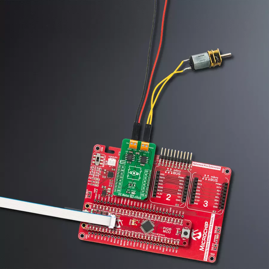
DC Motor 16 Click
Dev. board
Curiosity Nano with PIC18F57Q43
Compiler
NECTO Studio
MCU
PIC18F57Q43
Do you want to control handheld power tools easily? Add this brushed motor control solution and transform your project!
A
A
Hardware Overview
How does it work?
DC Motor 16 Click is based on the ZXBM5210, a single-chip solution for driving single-coil reversible direct current (DC) fans and motors from Diodes Incorporated. The driver output stage is designed to minimize audible switching noise and electromagnetic interference (EMI), ensuring a low-noise solution. The device has four motor operation modes: Standby, Forward, Reverse, and Brake Mode. These four modes are controlled by the FWD and REV pins routed to the RST and PWM pins of the mikroBUS™ used for controlling the motor rotation directions. All the internal circuits are turned off in the Standby mode to minimize power consumption, while the Brake mode allows the motor to stop quickly. The power consumption in the Standby mode is less than in the Brake mode. The signal change should be completed within 125μs to prevent the ZXBM5210 from entering the Standby mode during mode changes. The ZXBM5210 also possesses three modes of motor speed
control: VREF speed control mode, PWM speed control mode, and motor speed control by adjusting the supply voltage. Motor speed can be controlled by adjusting the duty cycle of the PWM signal while keeping the supply voltage pin at the nominal motor voltage or can be controlled by varying the supply voltage while the FWD and REV pins are set to either a logic high or low depending on needed motor direction. In PWM Mode, the input voltage on the Vref pin of the ZXBM5210 must be greater than or equal to the supply voltage value. The motor speed of the ZXBM5210 can be controlled by adjusting the DC voltage on the Vref pin. For this purpose, the DC Motor 16 click employs the MCP4161 digital potentiometer from Microchip, which allows setting the corresponding voltage value via the SPI serial interface. The potentiometer terminal B is fixed to the Zero-Scale wiper value (which corresponds to a wiper value of 0x00 for both 7-bit and 8-bit devices), while the
potentiometer terminal A is fixed connected to the Full-Scale wiper value (which corresponds to a wiper value of 0x100 for 8-bit devices or 0x80 for 7-bit devices). For this reason, it was chosen that when the user selects 0x100 as the desired value, the value on the Vref pin takes the value of supply voltage from the mikroBUS™ (VCC), while in the case of selecting 0x00 on the Vref pin value is equal to the 0.2*VCC. In this mode, FWD and REV pins are only used for direction control, and therefore high-frequency PWM control signal should not be applied to those pins. This Click board™ can operate with either 3.3V or 5V logic voltage levels selected via the VCC SEL jumper. This way, both 3.3V and 5V capable MCUs can use the communication lines properly. However, the Click board™ comes equipped with a library containing easy-to-use functions and an example code that can be used, as a reference, for further development.

Features overview
Development board
PIC18F57Q43 Curiosity Nano evaluation kit is a cutting-edge hardware platform designed to evaluate microcontrollers within the PIC18-Q43 family. Central to its design is the inclusion of the powerful PIC18F57Q43 microcontroller (MCU), offering advanced functionalities and robust performance. Key features of this evaluation kit include a yellow user LED and a responsive
mechanical user switch, providing seamless interaction and testing. The provision for a 32.768kHz crystal footprint ensures precision timing capabilities. With an onboard debugger boasting a green power and status LED, programming and debugging become intuitive and efficient. Further enhancing its utility is the Virtual serial port (CDC) and a debug GPIO channel (DGI
GPIO), offering extensive connectivity options. Powered via USB, this kit boasts an adjustable target voltage feature facilitated by the MIC5353 LDO regulator, ensuring stable operation with an output voltage ranging from 1.8V to 5.1V, with a maximum output current of 500mA, subject to ambient temperature and voltage constraints.

Microcontroller Overview
MCU Card / MCU

Architecture
PIC
MCU Memory (KB)
128
Silicon Vendor
Microchip
Pin count
48
RAM (Bytes)
8196
You complete me!
Accessories
Curiosity Nano Base for Click boards is a versatile hardware extension platform created to streamline the integration between Curiosity Nano kits and extension boards, tailored explicitly for the mikroBUS™-standardized Click boards and Xplained Pro extension boards. This innovative base board (shield) offers seamless connectivity and expansion possibilities, simplifying experimentation and development. Key features include USB power compatibility from the Curiosity Nano kit, alongside an alternative external power input option for enhanced flexibility. The onboard Li-Ion/LiPo charger and management circuit ensure smooth operation for battery-powered applications, simplifying usage and management. Moreover, the base incorporates a fixed 3.3V PSU dedicated to target and mikroBUS™ power rails, alongside a fixed 5.0V boost converter catering to 5V power rails of mikroBUS™ sockets, providing stable power delivery for various connected devices.

DC Gear Motor - 430RPM (3-6V) represents an all-in-one combination of a motor and gearbox, where the addition of gear leads to a reduction of motor speed while increasing the torque output. This gear motor has a spur gearbox, making it a highly reliable solution for applications with lower torque and speed requirements. The most critical parameters for gear motors are speed, torque, and efficiency, which are, in this case, 520RPM with no load and 430RPM at maximum efficiency, alongside a current of 60mA and a torque of 50g.cm. Rated for a 3-6V operational voltage range and clockwise/counterclockwise rotation direction, this motor represents an excellent solution for many functions initially performed by brushed DC motors in robotics, medical equipment, electric door locks, and much more.

Used MCU Pins
mikroBUS™ mapper
Take a closer look
Click board™ Schematic

Step by step
Project assembly

Start by selecting your development board and Click board™. Begin with the Curiosity Nano with PIC18F57Q43 as your development board.


Software Support
Library Description
This library contains API for DC Motor 16 Click driver.
Key functions:
void dcmotor16_set_direction( uint8_t dir )- Set motor directionvoid dcmotor16_ctrl_vref( uint16_t value )- Control motor VRef (speed)void dcmotor16_stop( void )- Motor stop
Open Source
Code example
The complete application code and a ready-to-use project are available through the NECTO Studio Package Manager for direct installation in the NECTO Studio. The application code can also be found on the MIKROE GitHub account.
/*!
 * @file main.c
 * @brief DCMotor16 Click example
 *
 * # Description
 * This example shows the capabilities of the DC Motor 16 Click board.
 *
 * The demo application is composed of two sections :
 *
 * ## Application Init
 * Initialization driver init.
 *
 * ## Application Task
 * Start motor example with change in motor direction and speed.
 *
 * @author Stefan Ilic
 *
 */

#include "board.h"
#include "log.h"
#include "dcmotor16.h"

static dcmotor16_t dcmotor16;
static log_t logger;

void application_init ( void ) {
    log_cfg_t log_cfg;  /**< Logger config object. */
    dcmotor16_cfg_t dcmotor16_cfg;  /**< Click config object. */

    /**
     * Logger initialization.
     * Default baud rate: 115200
     * Default log level: LOG_LEVEL_DEBUG
     * @note If USB_UART_RX and USB_UART_TX
     * are defined as HAL_PIN_NC, you will
     * need to define them manually for log to work.
     * See @b LOG_MAP_USB_UART macro definition for detailed explanation.
     */
    LOG_MAP_USB_UART( log_cfg );
    log_init( &logger, &log_cfg );
    log_info( &logger, " Application Init " );

    // Click initialization.

    dcmotor16_cfg_setup( &dcmotor16_cfg );
    DCMOTOR16_MAP_MIKROBUS( dcmotor16_cfg, MIKROBUS_1 );
    err_t init_flag  = dcmotor16_init( &dcmotor16, &dcmotor16_cfg );
    if ( SPI_MASTER_ERROR == init_flag ) {
        log_error( &logger, " Application Init Error. " );
        log_info( &logger, " Please, run program again... " );

        for ( ; ; );
    }
    log_info( &logger, " Application Task " );
}

void application_task ( void ) {
    uint16_t cnt;

    log_printf( &logger, ">> Motor start with direction [FORWARD] <<\r\n" );
    dcmotor16_set_direction( &dcmotor16, DCMOTOR16_DIR_FORWARD );
    for( cnt = 0; cnt <= 0x0100; cnt+= 25 ) {
        dcmotor16_ctrl_vref( &dcmotor16, cnt );
        Delay_ms ( 250 );
    }
    Delay_ms ( 1000 );
    Delay_ms ( 1000 );

    log_printf( &logger, ">> Motor stop \r\n" );
    dcmotor16_stop( &dcmotor16 );
    Delay_ms ( 1000 );

    log_printf( &logger, ">> Motor start with direction [BACKWARD] <<\r\n" );
    dcmotor16_set_direction( &dcmotor16, DCMOTOR16_DIR_BACKWARD );
    for( cnt = 0; cnt <= 0x0100; cnt+= 25 ) {
        dcmotor16_ctrl_vref( &dcmotor16, cnt );
        Delay_ms ( 250 );
    }
    Delay_ms ( 1000 );
    Delay_ms ( 1000 );

    log_printf( &logger, ">> Motor stop \r\n" );
    dcmotor16_stop( &dcmotor16 );
    Delay_ms ( 1000 );
}

int main ( void )
{
    /* Do not remove this line or clock might not be set correctly. */
    #ifdef PREINIT_SUPPORTED
    preinit();
    #endif

    application_init( );

    for ( ; ; )
    {
        application_task( );
    }

    return 0;
}

// ------------------------------------------------------------------------ END
Additional Support
Resources
Category:Brushed


