Conquer any task with A3910 and STM32F031K6
Uncompromising power, unmatched reliability

Published Oct 01, 2024
Click board™
DC Motor 21 Click
Dev. board
Nucleo 32 with STM32F031K6 MCU
Compiler
NECTO Studio
MCU
STM32F031K6
Experience the power of integrated motor control. Upgrade your future projects and unlock a new level of excellence!
A
A
Hardware Overview
How does it work?
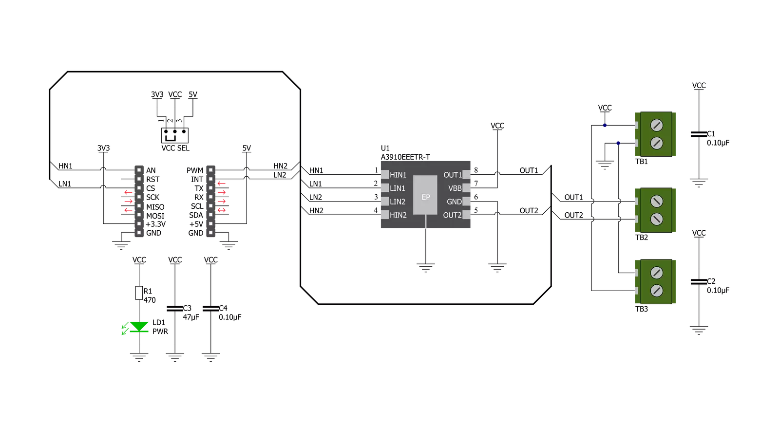
DC Motor 21 Click is based on the A3910, a dual half-bridge motor driver designed for low voltage power applications from Allegro Microsystems. This Click board™ is controlled via several GPIO pins of the mikroBUS™ socket and has a wide operating voltage range with an output current capacity of 500mA maximum. The integrated MOSFETs, which configure a half-bridge circuit inside the A3910, provide the possibility to drive dual DC motors and allow them to be used in the full-bridge configuration to drive a single bidirectional DC motor. Thanks to its plane features and benefits, this Click board™ is
targeted at the consumer market with end applications to low voltage equipment. Using an integrated MOS switch improves braking action for the motor, compared to implementation with a simple clamp diode. Besides, it also features built-in protection, such as crossover current and thermal shutdown protection, alongside “Sleep” Standby mode with zero drain-current. As mentioned in the product description, DC Motor 21 Click communicates with MCU using several GPIO pins. To turn ON the internal MOSFETs of the A3910, they need to be switched by the logic level, which is input to the control input pins: HN1, LN1,
HN2, and LN2 pins routed to the AN, CS, PWM, and INT pins of the mikroBUS™ socket. The Drive/Break/Coast/Sleep motor functions can be selected according to the state of its input control signals. This Click board™ can operate with either 3.3V or 5V logic voltage levels selected via the VCC SEL jumper. This way, both 3.3V and 5V capable MCUs can use the communication lines properly. The Click board™ comes equipped with a library containing easy-to-use functions and an example code that can be used, as a reference, for further development.

Features overview
Development board
Nucleo 32 with STM32F031K6 MCU board provides an affordable and flexible platform for experimenting with STM32 microcontrollers in 32-pin packages. Featuring Arduino™ Nano connectivity, it allows easy expansion with specialized shields, while being mbed-enabled for seamless integration with online resources. The
board includes an on-board ST-LINK/V2-1 debugger/programmer, supporting USB reenumeration with three interfaces: Virtual Com port, mass storage, and debug port. It offers a flexible power supply through either USB VBUS or an external source. Additionally, it includes three LEDs (LD1 for USB communication, LD2 for power,
and LD3 as a user LED) and a reset push button. The STM32 Nucleo-32 board is supported by various Integrated Development Environments (IDEs) such as IAR™, Keil®, and GCC-based IDEs like AC6 SW4STM32, making it a versatile tool for developers.

Microcontroller Overview
MCU Card / MCU

Architecture
ARM Cortex-M0
MCU Memory (KB)
32
Silicon Vendor
STMicroelectronics
Pin count
32
RAM (Bytes)
4096
You complete me!
Accessories
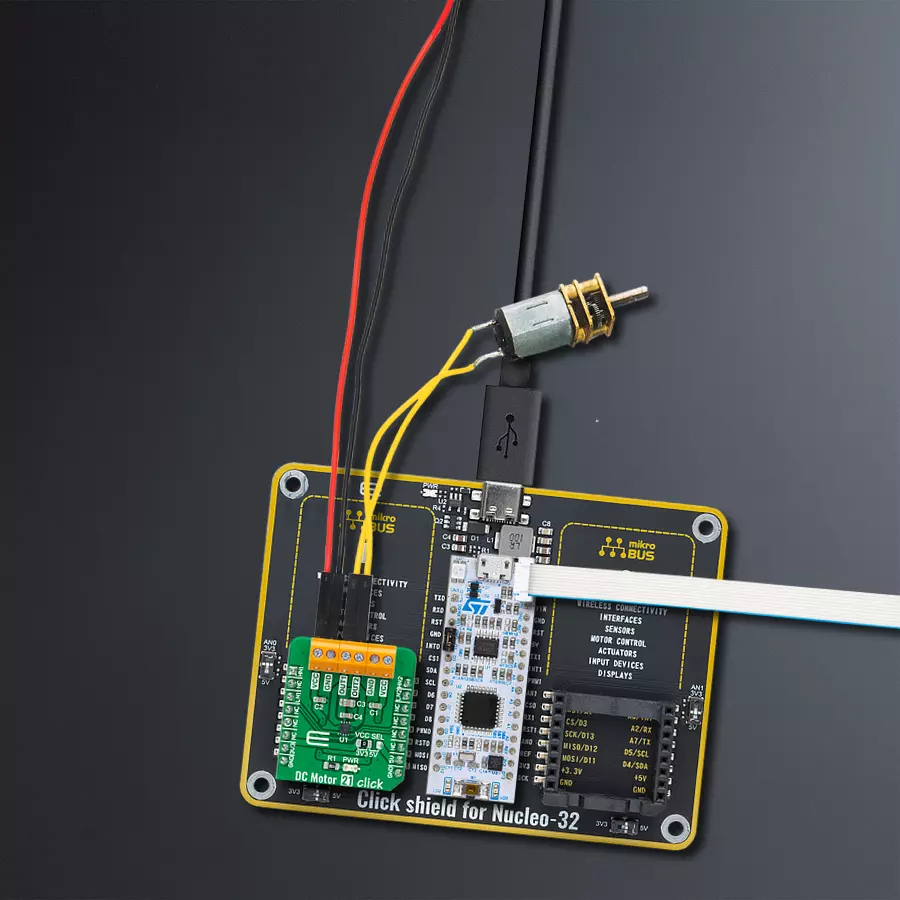
Click Shield for Nucleo-32 is the perfect way to expand your development board's functionalities with STM32 Nucleo-32 pinout. The Click Shield for Nucleo-32 provides two mikroBUS™ sockets to add any functionality from our ever-growing range of Click boards™. We are fully stocked with everything, from sensors and WiFi transceivers to motor control and audio amplifiers. The Click Shield for Nucleo-32 is compatible with the STM32 Nucleo-32 board, providing an affordable and flexible way for users to try out new ideas and quickly create prototypes with any STM32 microcontrollers, choosing from the various combinations of performance, power consumption, and features. The STM32 Nucleo-32 boards do not require any separate probe as they integrate the ST-LINK/V2-1 debugger/programmer and come with the STM32 comprehensive software HAL library and various packaged software examples. This development platform provides users with an effortless and common way to combine the STM32 Nucleo-32 footprint compatible board with their favorite Click boards™ in their upcoming projects.

DC Gear Motor - 430RPM (3-6V) represents an all-in-one combination of a motor and gearbox, where the addition of gear leads to a reduction of motor speed while increasing the torque output. This gear motor has a spur gearbox, making it a highly reliable solution for applications with lower torque and speed requirements. The most critical parameters for gear motors are speed, torque, and efficiency, which are, in this case, 520RPM with no load and 430RPM at maximum efficiency, alongside a current of 60mA and a torque of 50g.cm. Rated for a 3-6V operational voltage range and clockwise/counterclockwise rotation direction, this motor represents an excellent solution for many functions initially performed by brushed DC motors in robotics, medical equipment, electric door locks, and much more.

Used MCU Pins
mikroBUS™ mapper
Take a closer look
Click board™ Schematic
Step by step
Project assembly

Start by selecting your development board and Click board™. Begin with the Nucleo 32 with STM32F031K6 MCU as your development board.


Software Support
Library Description
This library contains API for DC Motor 21 Click driver.
Key functions:
dcmotor21_set_out_1- This function sets the state of output 1dcmotor21_set_out_2- This function sets the state of output 2
Open Source
Code example
The complete application code and a ready-to-use project are available through the NECTO Studio Package Manager for direct installation in the NECTO Studio. The application code can also be found on the MIKROE GitHub account.
/*!
 * @file main.c
 * @brief DC Motor 21 Click Example.
 *
 * # Description
 * This example demonstrates the use of DC Motor 21 Click board.
 *
 * The demo application is composed of two sections :
 *
 * ## Application Init
 * Initializes the driver and performs the Click default configuration.
 *
 * ## Application Task
 * In the span of six seconds, it drives the motor in one direction, then switches the direction,
 * and after that disconnects the motor. Each step will be logged on the USB UART where
 * you can track the program flow.
 *
 * @note
 * For this example, a DC motor should be connected to OUT1 and OUT2 lines.
 *
 * @author Stefan Filipovic
 *
 */

#include "board.h"
#include "log.h"
#include "dcmotor21.h"

static dcmotor21_t dcmotor21;   /**< DC Motor 21 Click driver object. */
static log_t logger;    /**< Logger object. */

void application_init ( void )
{
    log_cfg_t log_cfg;  /**< Logger config object. */
    dcmotor21_cfg_t dcmotor21_cfg;  /**< Click config object. */

    /**
     * Logger initialization.
     * Default baud rate: 115200
     * Default log level: LOG_LEVEL_DEBUG
     * @note If USB_UART_RX and USB_UART_TX
     * are defined as HAL_PIN_NC, you will
     * need to define them manually for log to work.
     * See @b LOG_MAP_USB_UART macro definition for detailed explanation.
     */
    LOG_MAP_USB_UART( log_cfg );
    log_init( &logger, &log_cfg );
    log_info( &logger, " Application Init " );

    // Click initialization.
    dcmotor21_cfg_setup( &dcmotor21_cfg );
    DCMOTOR21_MAP_MIKROBUS( dcmotor21_cfg, MIKROBUS_1 );
    if ( DIGITAL_OUT_UNSUPPORTED_PIN == dcmotor21_init( &dcmotor21, &dcmotor21_cfg ) )
    {
        log_error( &logger, " Communication init." );
        for ( ; ; );
    }

    dcmotor21_default_cfg ( &dcmotor21 );

    log_info( &logger, " Application Task " );
}

void application_task ( void )
{
    dcmotor21_set_out_1 ( &dcmotor21, DCMOTOR21_OUT_LOW );
    dcmotor21_set_out_2 ( &dcmotor21, DCMOTOR21_OUT_HIGH );
    log_printf( &logger, " \r\n Driving the motor...\r\n" );
    Delay_ms ( 1000 );
    Delay_ms ( 1000 );
    dcmotor21_set_out_1 ( &dcmotor21, DCMOTOR21_OUT_HIGH );
    dcmotor21_set_out_2 ( &dcmotor21, DCMOTOR21_OUT_LOW );
    log_printf( &logger, " Switch direction.\r\n" );
    Delay_ms ( 1000 );
    Delay_ms ( 1000 );
    dcmotor21_set_out_1 ( &dcmotor21, DCMOTOR21_OUT_HIGH_Z );
    dcmotor21_set_out_2 ( &dcmotor21, DCMOTOR21_OUT_HIGH_Z );
    log_printf( &logger, " The motor is disconnected.\r\n" );
    Delay_ms ( 1000 );
    Delay_ms ( 1000 );
}

int main ( void )
{
    /* Do not remove this line or clock might not be set correctly. */
    #ifdef PREINIT_SUPPORTED
    preinit();
    #endif

    application_init( );

    for ( ; ; )
    {
        application_task( );
    }

    return 0;
}

// ------------------------------------------------------------------------ END
Additional Support
Resources
Category:Brushed


