Create a complete DC motor driver solution with MP6515 and PIC18LF46K22
Enhance motor performance effortlessly

Published May 31, 2023
Click board™
H-Bridge 5 Click
Dev. board
EasyPIC v8
Compiler
NECTO Studio
MCU
PIC18LF46K22
Experience the pinnacle of control and power with our cutting-edge solution used to drive a solenoid or DC brush motor
A
A
Hardware Overview
How does it work?
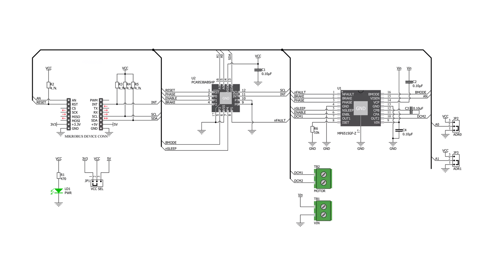
H-Bridge 5 Click is based on the MP6515, an H-bridge motor driver from Monolithic Power Systems (MPS). This Click board™ operates from a supply voltage of up to 30V and delivers a motor current of up to 1.5A. Its main applications include solenoid and DC brush motor driving. Its internal safety features include over-current protection, input over-voltage protection, undervoltage lockout (UVLO), and thermal shutdown. The MP6515 integrates four N-channel power MOSFETs with 2.8A peak current capability. It is designed to drive DC brush motors, solenoids, or other loads. Regarding current sensing, the current flowing in the two low-side MOSFETs is sensed with an internal current sensing circuit. A voltage that is proportional to the output
current is sourced on VISEN. Current is sensed when one of the low-side MOSFETs is turned on, including during slow decay (brake) mode. The load current applied to VISEN should be kept below 2mA, with no more than 500pF of capacitance. The H-Bridge 5 click also contains the PCA9538A, a low-voltage 8-bit General Purpose Input/Output (GPIO) expander from NXP with interrupt and reset for I2C-bus/SMBus applications. NXP I/O expander provides a simple solution when additional I/Os are needed while keeping interconnections to a minimum. Expanders provide communication between MP6515 and MCU, MCU control expander with I2C communication, and set output logic level for I/O pins. Data is exchanged
between the master and PCA9538A through write and read commands using I2C-bus. The two communication lines are a serial data line (SDA) and a serial clock line (SCL). Both lines must be connected to a positive supply via a pull-up resistor when connected to the output stages of a device. Data transfer may be initiated only when the bus is not busy. This Click board™ can operate with either 3.3V or 5V logic voltage levels selected via the VCC SEL jumper. This way, both 3.3V and 5V capable MCUs can use the communication lines properly. However, the Click board™ comes equipped with a library containing easy-to-use functions and an example code that can be used, as a reference, for further development.

Features overview
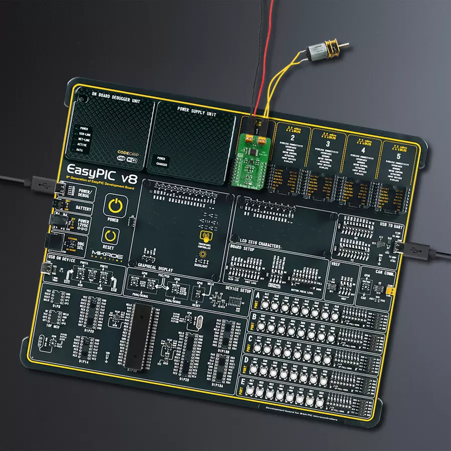
Development board
EasyPIC v8 is a development board specially designed for the needs of rapid development of embedded applications. It supports many high pin count 8-bit PIC microcontrollers from Microchip, regardless of their number of pins, and a broad set of unique functions, such as the first-ever embedded debugger/programmer. The development board is well organized and designed so that the end-user has all the necessary elements, such as switches, buttons, indicators, connectors, and others, in one place. Thanks to innovative manufacturing technology, EasyPIC v8 provides a fluid and immersive working experience, allowing access anywhere and under any
circumstances at any time. Each part of the EasyPIC v8 development board contains the components necessary for the most efficient operation of the same board. In addition to the advanced integrated CODEGRIP programmer/debugger module, which offers many valuable programming/debugging options and seamless integration with the Mikroe software environment, the board also includes a clean and regulated power supply module for the development board. It can use a wide range of external power sources, including a battery, an external 12V power supply, and a power source via the USB Type-C (USB-C) connector.
Communication options such as USB-UART, USB DEVICE, and CAN are also included, including the well-established mikroBUS™ standard, two display options (graphical and character-based LCD), and several different DIP sockets. These sockets cover a wide range of 8-bit PIC MCUs, from the smallest PIC MCU devices with only eight up to forty pins. EasyPIC v8 is an integral part of the Mikroe ecosystem for rapid development. Natively supported by Mikroe software tools, it covers many aspects of prototyping and development thanks to a considerable number of different Click boards™ (over a thousand boards), the number of which is growing every day.

Microcontroller Overview
MCU Card / MCU
Architecture
PIC
MCU Memory (KB)
64
Silicon Vendor
Microchip
Pin count
40
RAM (Bytes)
3896
You complete me!
Accessories
DC Gear Motor - 430RPM (3-6V) represents an all-in-one combination of a motor and gearbox, where the addition of gear leads to a reduction of motor speed while increasing the torque output. This gear motor has a spur gearbox, making it a highly reliable solution for applications with lower torque and speed requirements. The most critical parameters for gear motors are speed, torque, and efficiency, which are, in this case, 520RPM with no load and 430RPM at maximum efficiency, alongside a current of 60mA and a torque of 50g.cm. Rated for a 3-6V operational voltage range and clockwise/counterclockwise rotation direction, this motor represents an excellent solution for many functions initially performed by brushed DC motors in robotics, medical equipment, electric door locks, and much more.

Used MCU Pins
mikroBUS™ mapper
Take a closer look
Click board™ Schematic
Step by step
Project assembly

Start by selecting your development board and Click board™. Begin with the EasyPIC v8 as your development board.


Software Support
Library Description
This library contains API for H-Bridge 5 Click driver.
Key functions:
hbridge5_set_port- Function sets port.hbridge5_reverse- Puts motor into reverse motion.hbridge5_foreward- Puts motor into foreward motion.
Open Source
Code example
The complete application code and a ready-to-use project are available through the NECTO Studio Package Manager for direct installation in the NECTO Studio. The application code can also be found on the MIKROE GitHub account.
/*!
 * \file
 * \brief HBridge5 Click example
 *
 * # Description
 * This application controls DC motors and inductive loads.
 *
 * The demo application is composed of two sections :
 *
 * ## Application Init
 * Initalizes I2C driver, configures all ports as output and writes an initial log.
 *
 * ## Application Task
 * This example demonstrates the use of H-Bridge 5 Click board, by running dc motor forward,
 * then stoping and then running it in reverse and stoping again.
 *
 * \author MikroE Team
 *
 */
// ------------------------------------------------------------------- INCLUDES

#include "board.h"
#include "log.h"
#include "hbridge5.h"

// ------------------------------------------------------------------ VARIABLES

static hbridge5_t hbridge5;
static log_t logger;

// ------------------------------------------------------ APPLICATION FUNCTIONS

void application_init ( void )
{
    log_cfg_t log_cfg;
    hbridge5_cfg_t cfg;

    /**
     * Logger initialization.
     * Default baud rate: 115200
     * Default log level: LOG_LEVEL_DEBUG
     * @note If USB_UART_RX and USB_UART_TX
     * are defined as HAL_PIN_NC, you will
     * need to define them manually for log to work.
     * See @b LOG_MAP_USB_UART macro definition for detailed explanation.
     */
    LOG_MAP_USB_UART( log_cfg );
    log_init( &logger, &log_cfg );
    log_info( &logger, "---- Application Init ----" );

    //  Click initialization.

    hbridge5_cfg_setup( &cfg );
    HBRIDGE5_MAP_MIKROBUS( cfg, MIKROBUS_1 );
    hbridge5_init( &hbridge5, &cfg );
    hbridge5_default_cfg( &hbridge5 );
}

void application_task ( void )
{
    log_printf( &logger, "Mode - FORWARD\r\n" );
    hbridge5_forward( &hbridge5 );
    Delay_ms ( 1000 );
    Delay_ms ( 1000 );
    Delay_ms ( 1000 );

    log_printf( &logger, "Mode - SLEEP\r\n" );
    hbridge5_sleep( &hbridge5, HBRIDGE5_DISABLE_ALL_OUTPUT_PORT );
    Delay_ms ( 1000 );
    Delay_ms ( 1000 );
    Delay_ms ( 1000 );

    log_printf( &logger, "Mode - REVERSE\r\n" );
    hbridge5_reverse( &hbridge5 );
    Delay_ms ( 1000 );
    Delay_ms ( 1000 );
    Delay_ms ( 1000 );

    log_printf( &logger, "Mode - SLEEP\r\n" );
    hbridge5_sleep( &hbridge5, HBRIDGE5_DISABLE_ALL_OUTPUT_PORT );
    Delay_ms ( 1000 );
    Delay_ms ( 1000 );
    Delay_ms ( 1000 );
}

int main ( void )
{
    /* Do not remove this line or clock might not be set correctly. */
    #ifdef PREINIT_SUPPORTED
    preinit();
    #endif

    application_init( );

    for ( ; ; )
    {
        application_task( );
    }

    return 0;
}

// ------------------------------------------------------------------------ END


