Create a high-quality audio system with MA12070 and STM32L496AG
Turn up the beat and let your body move to the rhythm!
Published Jul 22, 2025
Click board™
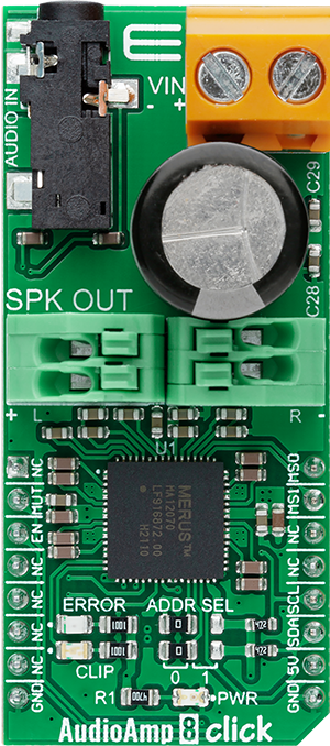
AudioAmp 8 Click
Dev. board
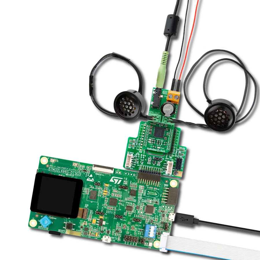
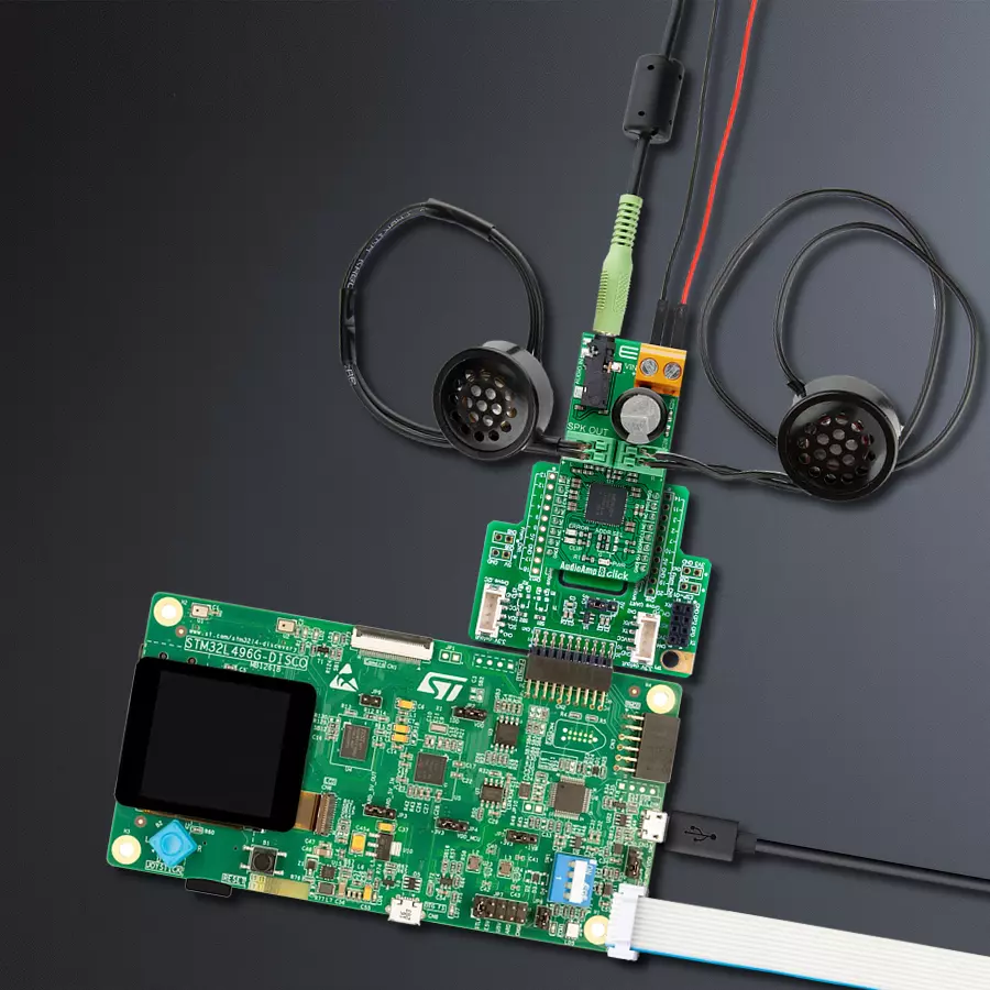
Discovery kit with STM32L496AG MCU
Compiler
NECTO Studio
MCU
STM32L496AG
Super-efficient audio power amplifier based on proprietary multi-level switching technology
A
A
Hardware Overview
How does it work?
AudioAmp 8 Click is based on the MA12070, a super-efficient audio power amplifier based on proprietary multi-level switching technology that enables low power loss during operation from Infineon Technologies. The MA12070 has an intelligent power management algorithm that applies automatic power mode selection during audio playback. In this state, the amplifier will seamlessly transition between three different power modes depending on the audio level to achieve optimal power loss, audio performance, and EMI. Alternatively, it is also possible to manually select the desired power mode for the MA12070 via a serial interface. The MA12070 communicates with MCU using the standard I2C 2-Wire interface that supports Standard (100 kHz) and Fast (400 kHz) modes of operation. It has a 7-bit slave address with the first five MSBs fixed to 01000. The user programs the address pins and determines the value of the last two LSBs
of the slave address, which can be selected by positioning onboard SMD jumpers labeled as ADDR SEL to an appropriate position marked as 0 or 1. This Click board™ supports an external power supply for the motor, which can be connected to the input terminal labeled as VIN and should be within the range of 6V to 26V, while the input audio can be brought to the input jack labeled as AUDIO IN and after specific processing reproduced on the speakers of the desired channel SPK OUT. The MA12070 is highly flexible regarding the configuration of the four power amplifier channels. It can be set to four different output configurations by setting the configuration pins MS0 and MS1, routed to the INT and PWM pins of the mikroBUS™ socket. In addition to these pins, this Click board™ uses a few more pins of the mikroBUS™ socket. The Enable pin, labeled as EN and routed to the CS pin of the mikroBUS™ socket, optimizes power consumption
used for power ON/OFF purposes, while the MUT pin routed to the RST pin allows users to mute audio on connected speakers. Besides, it is possible to detect operational irregularities, such as overcurrent and short-circuit detection. An indication of such a condition is performed using the red LED indicator labeled as ERROR, alongside an audio clipping indication accomplished using the blue LED indicator marked CLIP, indicating when audio output is close to clipping. This Click board™ can only be operated with a 5V logic voltage level. The board must perform appropriate logic voltage level conversion before using MCUs with different logic levels. However, the Click board™ comes equipped with a library containing functions and an example code that can be used as a reference for further development.

Features overview
Development board
The 32L496GDISCOVERY Discovery kit serves as a comprehensive demonstration and development platform for the STM32L496AG microcontroller, featuring an Arm® Cortex®-M4 core. Designed for applications that demand a balance of high performance, advanced graphics, and ultra-low power consumption, this kit enables seamless prototyping for a wide range of embedded solutions. With its innovative energy-efficient
architecture, the STM32L496AG integrates extended RAM and the Chrom-ART Accelerator, enhancing graphics performance while maintaining low power consumption. This makes the kit particularly well-suited for applications involving audio processing, graphical user interfaces, and real-time data acquisition, where energy efficiency is a key requirement. For ease of development, the board includes an onboard ST-LINK/V2-1
debugger/programmer, providing a seamless out-of-the-box experience for loading, debugging, and testing applications without requiring additional hardware. The combination of low power features, enhanced memory capabilities, and built-in debugging tools makes the 32L496GDISCOVERY kit an ideal choice for prototyping advanced embedded systems with state-of-the-art energy efficiency.

Microcontroller Overview
MCU Card / MCU

Architecture
ARM Cortex-M4
MCU Memory (KB)
1024
Silicon Vendor
STMicroelectronics
Pin count
169
RAM (Bytes)
327680
Used MCU Pins
mikroBUS™ mapper
Take a closer look
Click board™ Schematic

Step by step
Project assembly

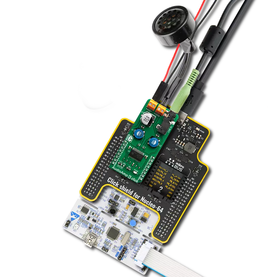
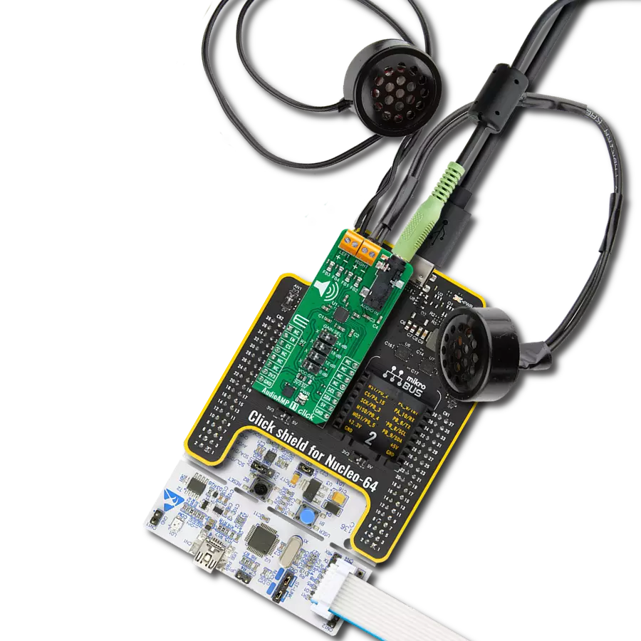
Start by selecting your development board and Click board™. Begin with the Discovery kit with STM32L496AG MCU as your development board.


Track your results in real time
Application Output
1. Application Output - In Debug mode, the 'Application Output' window enables real-time data monitoring, offering direct insight into execution results. Ensure proper data display by configuring the environment correctly using the provided tutorial.

2. UART Terminal - Use the UART Terminal to monitor data transmission via a USB to UART converter, allowing direct communication between the Click board™ and your development system. Configure the baud rate and other serial settings according to your project's requirements to ensure proper functionality. For step-by-step setup instructions, refer to the provided tutorial.

3. Plot Output - The Plot feature offers a powerful way to visualize real-time sensor data, enabling trend analysis, debugging, and comparison of multiple data points. To set it up correctly, follow the provided tutorial, which includes a step-by-step example of using the Plot feature to display Click board™ readings. To use the Plot feature in your code, use the function: plot(*insert_graph_name*, variable_name);. This is a general format, and it is up to the user to replace 'insert_graph_name' with the actual graph name and 'variable_name' with the parameter to be displayed.

Software Support
Library Description
This library contains API for Audio Amp 8 Click driver.
Key functions:
audioamp8_cfg_setup- Config Object Initialization function.audioamp8_init- Initialization function.audioamp8_default_cfg- Click Default Configuration function.
Open Source
Code example
The complete application code and a ready-to-use project are available through the NECTO Studio Package Manager for direct installation in the NECTO Studio. The application code can also be found on the MIKROE GitHub account.
/*!
 * @file main.c
 * @brief AudioAmp8 Click example
 *
 * # Description
 * This library contains API for AudioAmp 8 Click driver.
 * The library initializes and defines the I2C bus drivers
 * to write and read data from registers.
 *
 * The demo application is composed of two sections :
 *
 * ## Application Init
 * The initialization of I2C  module, log UART, and additional pins.
 * After the driver init and executing a default configuration,
 * the app performs a BTL signal configuration, configures power mode
 * and configures power mode profile.
 *
 * ## Application Task
 * This is an example that shows the use of a AudioAmp 8 Click board™.
 * Displays status monitoring for channel 0 or channel 1.
 * This task repeats once every 2 seconds.
 *
 * ## Additional Function
 * - static void channel_status_monitoring ( uint8_t ch_sel ) - The function displays the status monitoring channel.
 *
 * @author Nenad Filipovic
 *
 */

#include "board.h"
#include "log.h"
#include "audioamp8.h"

static audioamp8_t audioamp8;
static log_t logger;
static audioamp8_pwr_mon_cfg_t pwr_mode;
static audioamp8_pwr_mod_profile_cfg_t pm_profile;
static audioamp8_monitor_channel_t ch_mon;

static void channel_status_monitoring ( uint8_t ch_sel )
{
    audioamp8_channel_monitoring( &audioamp8, ch_sel, &ch_mon );
    Delay_ms ( 100 );
    log_printf( &logger, " Frequency mode    : %d\r\n", ( uint16_t ) ch_mon.freq_mode );
    log_printf( &logger, " Power mode        : %d\r\n", ( uint16_t ) ch_mon.pwr_mode );

    log_printf( &logger, " Channel %d mute    : ", ( uint16_t ) ch_sel );
    if ( ch_mon.mute_mon == AUDIOAMP8_SET_ENABLE )
    {
        log_printf( &logger, "ON\r\n" );
    }
    else
    {
        log_printf( &logger, "OFF\r\n" );
    }

    log_printf( &logger, " Channel %d VDD     : ", ( uint16_t ) ch_sel );
    if ( ch_mon.vdd_mon == AUDIOAMP8_SET_ENABLE )
    {
        log_printf( &logger, "ON\r\n" );
    }
    else
    {
        log_printf( &logger, "OFF\r\n" );
    }

    log_printf( &logger, " Channel %d PVDD    : ", ( uint16_t ) ch_sel );
    if ( ch_mon.pvdd_mon == AUDIOAMP8_SET_ENABLE )
    {
        log_printf( &logger, "ON\r\n" );
    }
    else
    {
        log_printf( &logger, "OFF\r\n" );
    }

    log_printf( &logger, " Cfly1 protection  : " );
    if ( ch_mon.cfly1_mon == AUDIOAMP8_SET_ENABLE )
    {
        log_printf( &logger, "ON\r\n" );
    }
    else
    {
        log_printf( &logger, "OFF\r\n" );
    }

    log_printf( &logger, " Cfly2 protection  : " );
    if ( ch_mon.cfly2_mon == AUDIOAMP8_SET_ENABLE )
    {
        log_printf( &logger, "ON\r\n" );
    }
    else
    {
        log_printf( &logger, "OFF\r\n" );
    }

    log_printf( &logger, " Current protection: " );
    if ( ch_mon.ovc_prot == AUDIOAMP8_SET_ENABLE )
    {
        log_printf( &logger, "ON\r\n" );
    }
    else
    {
        log_printf( &logger, "OFF\r\n" );
    }

    log_printf( &logger, " Modulation index  : %d\r\n", ( uint16_t ) ch_mon.modul_index_mon );
    log_printf( &logger, "-------------------------\r\n" );
}

void application_init ( void )
{
    log_cfg_t log_cfg;  /**< Logger config object. */
    audioamp8_cfg_t audioamp8_cfg;  /**< Click config object. */

    /**
     * Logger initialization.
     * Default baud rate: 115200
     * Default log level: LOG_LEVEL_DEBUG
     * @note If USB_UART_RX and USB_UART_TX
     * are defined as HAL_PIN_NC, you will
     * need to define them manually for log to work.
     * See @b LOG_MAP_USB_UART macro definition for detailed explanation.
     */
    LOG_MAP_USB_UART( log_cfg );
    log_init( &logger, &log_cfg );
    log_info( &logger, " Application Init " );

    // Click initialization.
    audioamp8_cfg_setup( &audioamp8_cfg );
    AUDIOAMP8_MAP_MIKROBUS( audioamp8_cfg, MIKROBUS_1 );
    err_t init_flag = audioamp8_init( &audioamp8, &audioamp8_cfg );
    if ( I2C_MASTER_ERROR == init_flag )
    {
        log_error( &logger, " Application Init Error. " );
        log_info( &logger, " Please, run program again... " );
        for ( ; ; );
    }

    if ( AUDIOAMP8_ERROR == audioamp8_default_cfg ( &audioamp8 ) )
    {
        log_error( &logger, " Default configuration." );
        for ( ; ; );
    }
    log_info( &logger, " Application Task " );
    log_printf( &logger, "-------------------------\r\n" );
    Delay_ms ( 1000 );
}

void application_task ( void )
{
    channel_status_monitoring( AUDIOAMP8_SET_MON_CH_0 );
    Delay_ms ( 1000 );
}

int main ( void )
{
    /* Do not remove this line or clock might not be set correctly. */
    #ifdef PREINIT_SUPPORTED
    preinit();
    #endif

    application_init( );

    for ( ; ; )
    {
        application_task( );
    }

    return 0;
}

// ------------------------------------------------------------------------ END
Additional Support
Resources
Category:Amplifier