Detect magnetic fields across three axes (X, Y, and Z) with the MLX90394 and PIC32MZ2048EFM100
Triaxis® Hall technology magnetometer for high-precision magnetic position sensing

Published Jul 16, 2024
Click board™
3D Hall 14 Click
Dev. board
Curiosity PIC32 MZ EF
Compiler
NECTO Studio
MCU
PIC32MZ2048EFM100
Accurately detect movement and orientation of magnetic object in all three spatial dimensions, enabling precise position tracking in various applications
A
A
Hardware Overview
How does it work?
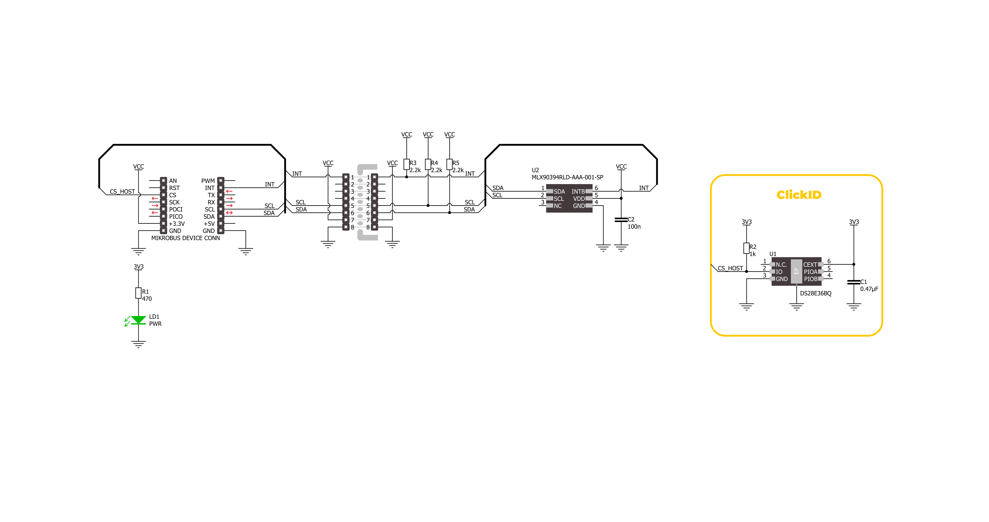
3D Hall 14 Click is based on the MLX90394, a high-precision 3-axis magnetometer from Melexis, which uses the Triaxis® Hall technology to deliver exceptional performance and enhance position sensing in various applications. The MLX90394 is made for micropower applications, making it an excellent choice for battery-powered solutions. It accurately measures magnetic fields along three axes (X, Y, and Z) and converts these measurements and IC temperature into 16-bit words. These data points are then communicated through an I2C interface. The sensor offers flexibility in operation, allowing for measurements to be taken either on demand or continuously, with user-selectable refresh rates. Despite its compact size, the MLX90394 excels in noise performance and maintains low power consumption across various configurations. One of the standout features of the MLX90394 is its intelligent wake-up modes, which enable the entire system to enter a deep sleep state until a magnetic field change is
detected. This detection can be based on different criteria: a change from an initial measurement (Static Delta), a change from the previous measurement (Dynamic Delta), or surpassing a predefined threshold (Absolute). This functionality ensures efficient power management by toggling the device between active and sleep modes, capturing both busy and slowly changing magnetic fields effectively. As mentioned, the 3D Hall 14 Click is ideal for various applications. It can be used in battery-powered tools, household appliances (white goods), industrial machinery, smart home devices, home security systems, and many other contexts where precise and reliable position sensing is crucial. This Click board™ is designed in a unique format supporting the newly introduced MIKROE feature called "Click Snap." Unlike the standardized version of Click boards, this feature allows the main sensor area to become movable by breaking the PCB, opening up many new possibilities for implementation. Thanks to the
Snap feature, the MLX9039 can operate autonomously by accessing its signals directly on the pins marked 1-8. Additionally, the Snap part includes a specified and fixed screw hole position, enabling users to secure the Snap board in their desired location. 3D Hall 14 Click uses a standard 2-Wire I2C interface to communicate with the host MCU with fast-mode support and frequencies up to 1MHz. In addition to I2C pins, this Click board™ also has the interrupt signal on the INT pin of the mikroBUS™ socket to provide a notification that violates programmed thresholds. This interrupt can serve as a wake-up on change (WOC) interrupt output or a synchronization output. This Click board™ can be operated only with a 3.3V logic voltage level. The board must perform appropriate logic voltage level conversion before using MCUs with different logic levels. Also, it comes equipped with a library containing functions and an example code that can be used as a reference for further development.

Features overview
Development board
Curiosity PIC32 MZ EF development board is a fully integrated 32-bit development platform featuring the high-performance PIC32MZ EF Series (PIC32MZ2048EFM) that has a 2MB Flash, 512KB RAM, integrated FPU, Crypto accelerator, and excellent connectivity options. It includes an integrated programmer and debugger, requiring no additional hardware. Users can expand
functionality through MIKROE mikroBUS™ Click™ adapter boards, add Ethernet connectivity with the Microchip PHY daughter board, add WiFi connectivity capability using the Microchip expansions boards, and add audio input and output capability with Microchip audio daughter boards. These boards are fully integrated into PIC32’s powerful software framework, MPLAB Harmony,
which provides a flexible and modular interface to application development a rich set of inter-operable software stacks (TCP-IP, USB), and easy-to-use features. The Curiosity PIC32 MZ EF development board offers expansion capabilities making it an excellent choice for a rapid prototyping board in Connectivity, IOT, and general-purpose applications.

Microcontroller Overview
MCU Card / MCU

Architecture
PIC32
MCU Memory (KB)
2048
Silicon Vendor
Microchip
Pin count
100
RAM (Bytes)
524288
Used MCU Pins
mikroBUS™ mapper
Take a closer look
Click board™ Schematic
Step by step
Project assembly

Start by selecting your development board and Click board™. Begin with the Curiosity PIC32 MZ EF as your development board.


Software Support
Library Description
This library contains API for 3D Hall 14 Click driver.
Key functions:
c3dhall14_get_magnetic_flux- This function reads the raw values of X, Y, and Z axis and converts them to magnetic flux data in microTesla.c3dhall14_get_temperature- This function reads the raw temperature value and converts it to Celsius.c3dhall14_set_range- This function sets the magnetic flux measurement range.
Open Source
Code example
The complete application code and a ready-to-use project are available through the NECTO Studio Package Manager for direct installation in the NECTO Studio. The application code can also be found on the MIKROE GitHub account.
/*!
 * @file main.c
 * @brief 3D Hall 14 Click example
 *
 * # Description
 * This example demonstrates the use of 3D Hall 14 Click board by reading
 * the magnetic field strength from 3 axes and the sensor internal temperature.
 *
 * The demo application is composed of two sections :
 *
 * ## Application Init
 * Initializes the driver and performs the Click default configuration.
 *
 * ## Application Task
 * Reads data from the sensor and displays them on the USB UART every 200ms.
 *
 * @author Stefan Filipovic
 *
 */

#include "board.h"
#include "log.h"
#include "c3dhall14.h"

static c3dhall14_t c3dhall14;
static log_t logger;

void application_init ( void )
{
    log_cfg_t log_cfg;  /**< Logger config object. */
    c3dhall14_cfg_t c3dhall14_cfg;  /**< Click config object. */

    /**
     * Logger initialization.
     * Default baud rate: 115200
     * Default log level: LOG_LEVEL_DEBUG
     * @note If USB_UART_RX and USB_UART_TX
     * are defined as HAL_PIN_NC, you will
     * need to define them manually for log to work.
     * See @b LOG_MAP_USB_UART macro definition for detailed explanation.
     */
    LOG_MAP_USB_UART( log_cfg );
    log_init( &logger, &log_cfg );
    log_info( &logger, " Application Init " );

    // Click initialization.
    c3dhall14_cfg_setup( &c3dhall14_cfg );
    C3DHALL14_MAP_MIKROBUS( c3dhall14_cfg, MIKROBUS_1 );
    if ( I2C_MASTER_ERROR == c3dhall14_init( &c3dhall14, &c3dhall14_cfg ) )
    {
        log_error( &logger, " Communication init." );
        for ( ; ; );
    }

    if ( C3DHALL14_ERROR == c3dhall14_default_cfg ( &c3dhall14 ) )
    {
        log_error( &logger, " Default configuration." );
        for ( ; ; );
    }

    log_info( &logger, " Application Task " );
}

void application_task ( void )
{
    float x_axis = 0;
    float y_axis = 0;
    float z_axis = 0;
    float temperature = 0;
    if ( C3DHALL14_OK == c3dhall14_get_magnetic_flux ( &c3dhall14, &x_axis, &y_axis, &z_axis ) )
    {
        log_printf( &logger, " X-axis: %.1f uT\r\n", x_axis );
        log_printf( &logger, " Y-axis: %.1f uT\r\n", y_axis );
        log_printf( &logger, " Z-axis: %.1f uT\r\n", z_axis );
    }
    if ( C3DHALL14_OK == c3dhall14_get_temperature ( &c3dhall14, &temperature ) )
    {
        log_printf( &logger, " Internal temperature: %.2f C\r\n\n", temperature );
    }
}

int main ( void )
{
    /* Do not remove this line or clock might not be set correctly. */
    #ifdef PREINIT_SUPPORTED
    preinit();
    #endif

    application_init( );

    for ( ; ; )
    {
        application_task( );
    }

    return 0;
}

// ------------------------------------------------------------------------ END
Additional Support
Resources
Category:Magnetic


