Provide Bluetooth connectivity for any embedded application with RN-41 and PIC32MZ2048EFM100
Connect and share data without the need for physical cables
Published Nov 03, 2023
Click board™
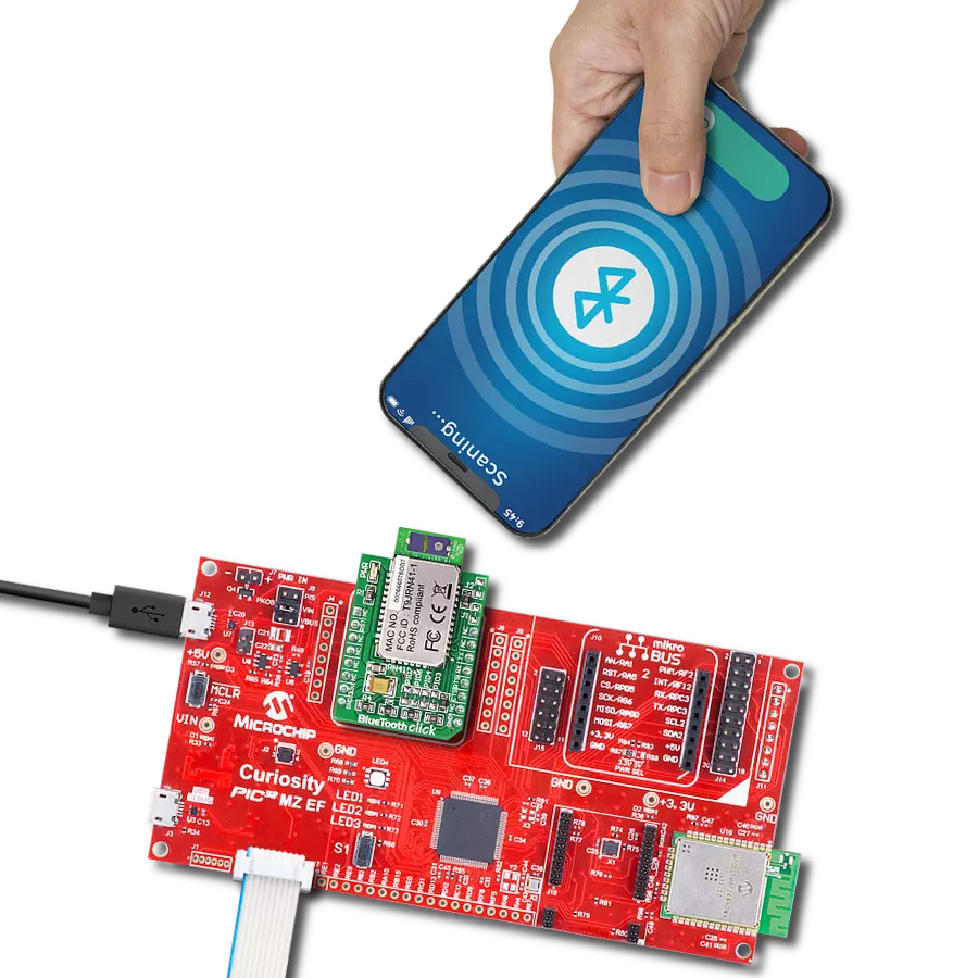
Bluetooth Click
Dev. board
Curiosity PIC32 MZ EF
Compiler
NECTO Studio
MCU
PIC32MZ2048EFM100
Add Bluetooth connectivity into your embedded projects with extended range, compatibility with Bluetooth version 2.1 + EDR, and resilience in high-interference environments
A
A
Hardware Overview
How does it work?
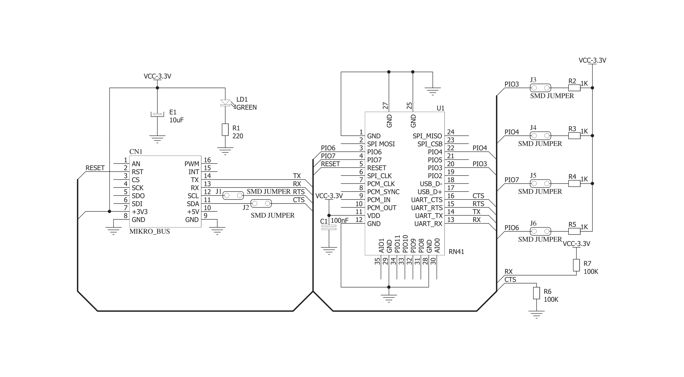
Bluetooth Click is based on the RN-41, a Class 1 Bluetooth module from Microchip. The auto-discovery/pairing on this module does not require software configuration. It has a 15dBm output transmitter with -80dBm of typical receive sensitivity for transmitting data using FHSS/GFSK modulation on 79 channels and at 1MHz intervals. The 3Mbps data rate communication is secured with 128-bit encryption, with error correction, which guarantees packet delivery. The 3Mbps data rate is a maximum that can be achieved in a burst in HCI mode, while the 1.5Mbps is sustained. To communicate with the host MCU, the Bluetooth Click uses the UART interface with commonly used
UART RX and TX as its default communication protocol. It can operate at baud rate speeds from 1200bps to 921Kbps, while non-standard baud rates can be programmed. The hardware flow control pins UART CTS/RTS are disabled and can be enabled by soldering J1 and J2 jumpers. The RN-41 module can be programmed over the UART interface of the mikroBUS™ socket with a simple ASCI command language similar to the Hayes AT protocol. The module can be reset via the RST pin with active LOW. This Click board™ features four more jumpers labeled PIO3, PIO4, PIO6, and PIO7. The auto-discovery function can be enabled by soldering jumper PIO3. To set the factory default
values, you should solder the PIO4 jumper, and this feature is critical when the module has been misconfigured. The auto-master mode can be set by soldering the PIO6 jumper; the standard application runs on SPP/DUN Master and Slave. The firmware can set the baud rate but can also be forced to 9600bps by soldering the PIO7 jumper. This Click board™ can be operated only with a 3.3V logic voltage level. The board must perform appropriate logic voltage level conversion before using MCUs with different logic levels. Also, it comes equipped with a library containing functions and an example code that can be used as a reference for further development.

Features overview
Development board
Curiosity PIC32 MZ EF development board is a fully integrated 32-bit development platform featuring the high-performance PIC32MZ EF Series (PIC32MZ2048EFM) that has a 2MB Flash, 512KB RAM, integrated FPU, Crypto accelerator, and excellent connectivity options. It includes an integrated programmer and debugger, requiring no additional hardware. Users can expand
functionality through MIKROE mikroBUS™ Click™ adapter boards, add Ethernet connectivity with the Microchip PHY daughter board, add WiFi connectivity capability using the Microchip expansions boards, and add audio input and output capability with Microchip audio daughter boards. These boards are fully integrated into PIC32’s powerful software framework, MPLAB Harmony,
which provides a flexible and modular interface to application development a rich set of inter-operable software stacks (TCP-IP, USB), and easy-to-use features. The Curiosity PIC32 MZ EF development board offers expansion capabilities making it an excellent choice for a rapid prototyping board in Connectivity, IOT, and general-purpose applications.

Microcontroller Overview
MCU Card / MCU

Architecture
PIC32
MCU Memory (KB)
2048
Silicon Vendor
Microchip
Pin count
100
RAM (Bytes)
524288
Used MCU Pins
mikroBUS™ mapper
Take a closer look
Click board™ Schematic
Step by step
Project assembly

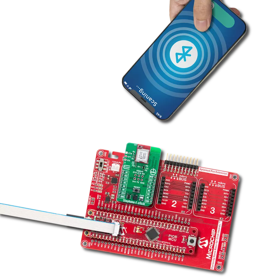
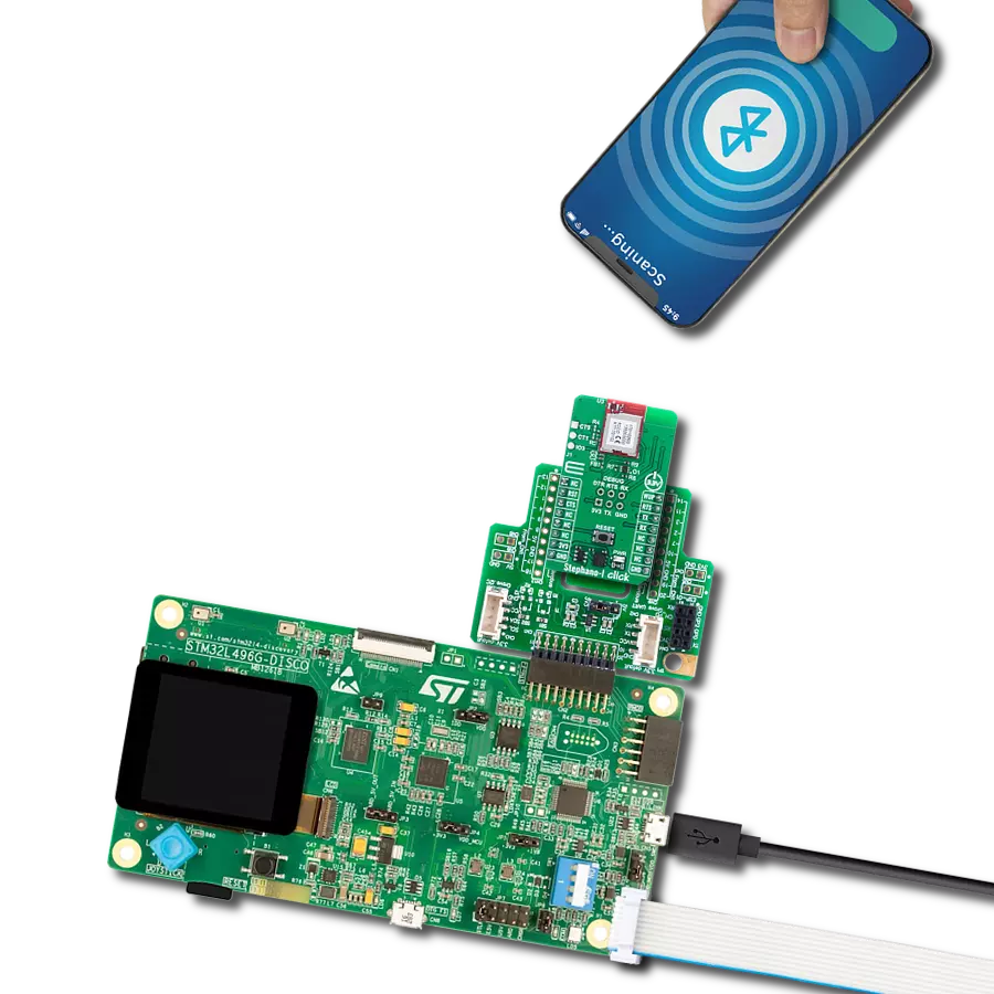
Start by selecting your development board and Click board™. Begin with the Curiosity PIC32 MZ EF as your development board.


Track your results in real time
Application Output
1. Application Output - In Debug mode, the 'Application Output' window enables real-time data monitoring, offering direct insight into execution results. Ensure proper data display by configuring the environment correctly using the provided tutorial.

2. UART Terminal - Use the UART Terminal to monitor data transmission via a USB to UART converter, allowing direct communication between the Click board™ and your development system. Configure the baud rate and other serial settings according to your project's requirements to ensure proper functionality. For step-by-step setup instructions, refer to the provided tutorial.

3. Plot Output - The Plot feature offers a powerful way to visualize real-time sensor data, enabling trend analysis, debugging, and comparison of multiple data points. To set it up correctly, follow the provided tutorial, which includes a step-by-step example of using the Plot feature to display Click board™ readings. To use the Plot feature in your code, use the function: plot(*insert_graph_name*, variable_name);. This is a general format, and it is up to the user to replace 'insert_graph_name' with the actual graph name and 'variable_name' with the parameter to be displayed.

Software Support
Library Description
This library contains API for Bluetooth Click driver.
Key functions:
bluetooth_enter_command_mode- The function enter the command mode of the RN-41 Bluetooth module on Bluetooth Click board.bluetooth_set_authentication- The function set the authentication value to the RN-41 Bluetooth module on Bluetooth Click board.bluetooth_set_security_pin_code- The function set security pin code string to the RN-41 Bluetooth module on Bluetooth Click board.
Open Source
Code example
The complete application code and a ready-to-use project are available through the NECTO Studio Package Manager for direct installation in the NECTO Studio. The application code can also be found on the MIKROE GitHub account.
/*!
 * \file
 * \brief Bluetooth Click example
 *
 * # Description
 * This example reads and processes data from Bluetooth Clicks.
 *
 * The demo application is composed of two sections :
 *
 * ## Application Init
 * Initializes driver and wake-up module.
 *
 * ## Application Task
 * Reads the received data.
 *
 * ## Additional Function
 * - bluetooth_process ( ) - Logs all received messages on UART, and sends the certain message back to the connected device.
 *
 * *note:*
 * Before starting to use this Click, it must be paired with other device.
 *
 * \author MikroE Team
 *
 */
// ------------------------------------------------------------------- INCLUDES

#include "board.h"
#include "log.h"
#include "bluetooth.h"
#include "string.h"

#define PROCESS_COUNTER 20
#define PROCESS_RX_BUFFER_SIZE 100
#define PROCESS_PARSER_BUFFER_SIZE 100

// ------------------------------------------------------------------ VARIABLES

static bluetooth_t bluetooth;
static log_t logger;

uint8_t DEVICE_NAME_DATA[ 20 ] = { 'B', 'l', 'u', 'e', 't', 'o', 'o', 't', 'h', 'C', 'l', 'i', 'c', 'k' };
uint8_t EXTENDED_STRING_DATA[ 10 ] = { 'S', 'l', 'a', 'v', 'e' };
uint8_t PIN_CODE_DATA[ 10 ] = { '1', '2', '3', '4' };
static char current_parser_buf[ PROCESS_PARSER_BUFFER_SIZE ];

// ------------------------------------------------------- ADDITIONAL FUNCTIONS

static int8_t bluetooth_process ( char * response )
{
    int32_t rsp_size;
    uint16_t rsp_cnt = 0;

    char uart_rx_buffer[ PROCESS_RX_BUFFER_SIZE ] = { 0 };
    uint8_t check_buf_cnt;
    uint8_t process_cnt = PROCESS_COUNTER;

    // Clear current buffer
    memset( current_parser_buf, 0, PROCESS_PARSER_BUFFER_SIZE );

    while( process_cnt != 0 )
    {
        rsp_size = bluetooth_generic_read( &bluetooth, uart_rx_buffer, PROCESS_RX_BUFFER_SIZE );

        if ( rsp_size > 0 )
        {
            // Validation of the received data
            for ( check_buf_cnt = 0; check_buf_cnt < rsp_size; check_buf_cnt++ )
            {
                if ( uart_rx_buffer[ check_buf_cnt ] == 0 )
                {
                    uart_rx_buffer[ check_buf_cnt ] = 13;
                }
            }
            // Storages data in current buffer
            rsp_cnt += rsp_size;
            if ( rsp_cnt < PROCESS_PARSER_BUFFER_SIZE )
            {
                strncat( current_parser_buf, uart_rx_buffer, rsp_size );
            }

            // Clear RX buffer
            memset( uart_rx_buffer, 0, PROCESS_RX_BUFFER_SIZE );

            log_printf( &logger, "%s", current_parser_buf );

            if ( strstr( current_parser_buf, "ERR" ) ) {
               Delay_100ms( );
               return -1;
            }

            if ( strstr( current_parser_buf, response ) ) {
               Delay_100ms( );
               return 1;
            }

            if ( strstr( current_parser_buf, "Hello" ) ) {
                bluetooth_generic_write( &bluetooth, "MikroE\r\n", 8 );
                Delay_100ms( );
            }
        }
        else
        {
            process_cnt--;

            // Process delay
            Delay_ms ( 100 );
        }
    }

    return 0;
}

// ------------------------------------------------------ APPLICATION FUNCTIONS

void application_init ( void )
{
    log_cfg_t log_cfg;
    bluetooth_cfg_t cfg;

    /**
     * Logger initialization.
     * Default baud rate: 115200
     * Default log level: LOG_LEVEL_DEBUG
     * @note If USB_UART_RX and USB_UART_TX
     * are defined as HAL_PIN_NC, you will
     * need to define them manually for log to work.
     * See @b LOG_MAP_USB_UART macro definition for detailed explanation.
     */
    LOG_MAP_USB_UART( log_cfg );
    log_init( &logger, &log_cfg );
    log_info( &logger, "---- Application Init ----" );

    //  Click initialization.

    bluetooth_cfg_setup( &cfg );
    BLUETOOTH_MAP_MIKROBUS( cfg, MIKROBUS_1 );
    bluetooth_init( &bluetooth, &cfg );

    Delay_ms ( 500 );

    log_printf( &logger, "Configuring the module...\n" );

    do
    {
        log_printf( &logger, " --- Command mode --- \r\n" );
        bluetooth_enter_command_mode( &bluetooth );
    }
    while( bluetooth_process( "CMD" ) != 1 );

    do
    {
        log_printf( &logger, " --- Device name --- \r\n" );
        bluetooth_set_device_name( &bluetooth, &DEVICE_NAME_DATA[ 0 ] );
    }
    while( bluetooth_process( "AOK" ) != 1 );

    do
    {
        log_printf( &logger, " --- Status string --- \r\n" );
        bluetooth_set_extended_status_string( &bluetooth, &EXTENDED_STRING_DATA[ 0 ] );
    }
    while( bluetooth_process( "AOK" ) != 1 );

    do
    {
        log_printf( &logger, " --- Operating mode --- \r\n" );
        bluetooth_set_operating_mode( &bluetooth, 0 );
    }
    while( bluetooth_process( "AOK" ) != 1 );

    do
    {
        log_printf( &logger, " --- Authentication --- \r\n" );
        bluetooth_set_authentication( &bluetooth, 1 );
    }
    while( bluetooth_process( "AOK" ) != 1 );

    do
    {
        log_printf( &logger, " --- Pin code --- \r\n" );
        bluetooth_set_security_pin_code( &bluetooth, &PIN_CODE_DATA[ 0 ] );
    }
    while( bluetooth_process( "AOK" ) != 1 );

    do
    {
        log_printf( &logger, " --- Exit command mode --- \r\n" );
        bluetooth_exit_command_mode( &bluetooth );
    }
    while( bluetooth_process( "END" ) != 1 );

    log_printf( &logger, "The module has been configured.\n" );
}

void application_task ( void )
{
    bluetooth_process( "AOK" );
}

int main ( void )
{
    /* Do not remove this line or clock might not be set correctly. */
    #ifdef PREINIT_SUPPORTED
    preinit();
    #endif

    application_init( );

    for ( ; ; )
    {
        application_task( );
    }

    return 0;
}


// ------------------------------------------------------------------------ END