Ensure the security and visibility of your assets with IN100 and PIC18F57Q43
The future of user interaction

Published Feb 13, 2024
Click board™
NanoBeacon Click
Dev. board
Curiosity Nano with PIC18F57Q43
Compiler
NECTO Studio
MCU
PIC18F57Q43
Effortlessly link devices, creating a network that adapts to your needs and ensures a seamless flow of information in any environment.
A
A
Hardware Overview
How does it work?
NanoBeacon Click is based on the IN100, a versatile and compact part of InPlay's NanoBeacon™ SoC product family that operates as a Bluetooth low energy beacon in the 2.4GHz frequency band. Packed with advanced features, this SoC boasts an efficient and configurable state machine, ensuring optimal performance. It incorporates non-volatile memory for storing user-defined data payload and a data SRAM for dynamic data storage. The IN100 further includes an analog-to-digital converter, a powerful security engine supporting AES-128 and EAX encryption, and a True Random Number Generator (TRNG) for enhanced security. It also offers a unique proprietary beacon mode, available in either the 2.4GHz ISM frequency band or the MedRadio frequency bands. Enclosed in a small QFN package, this device offers a seamless and secure solution for a wide range of Industrial Internet of Things (IIoT) applications. With its user-friendly design, this device eliminates the need for complex Bluetooth-related software programming. Once configured, it automatically transmits either BLE advertising or proprietary-format advertising packets, allowing for effortless operation. The IN100 features two types of built-in memory: a 4Kb OTP memory for storing user advertising data payload, security key, and predefined register settings, and a 4KB SRAM for dynamic advertising data storage. The SRAM retains data in Sleep mode while only the always-on (AON) domain remains active. The IN100 offers an extensive array of supported sensor interface protocols, ensuring compatibility with a wide
range of sensor devices. Additionally, it supports popular beacon formats such as iBeacon, Eddystone, and even custom beacon formats, allowing for seamless integration into various ecosystems. This Click board™ communicates with MCU using the UART interface with commonly used UART RX and TX pins. It operates at 115200 bps by default configuration to transmit and exchange data with the host MCU. Also, the IN100 enables on-the-fly changes to the advertising data payload and control mode through its UART interface. While UART communication can be used as the IN100's primary mode of communication with the MCU, an additionally supported interface, the I2C 2-wire interface, can be used to communicate with additional external sensors connected to this Click board™ via its onboard stacking headers of the mikroBUS™ socket. As previously stated, the OTP memory stores the user's advertising data payload, security key, and predefined register settings. This memory is programmed only once before usage. Switch the OTP SEL switch to ON to program the desired configuration into the device's one-time programmable memory. This action will effectively 'burn' the configuration into the tag's OTP memory. After the configuration has been burned, the power supply to the Click board™ must be disconnected and reconnected (or reset the board) to initiate the tag's execution based on its programmed behavior. This Click board™ comes with a miniature coaxial U.FL series antenna connector, which allows connecting the appropriate antenna for improved range and
received signal strength. Besides the UART pins, the NanoBeacon Click also employs other pins of the mikroBUS™ socket to enhance its functionality. For example, the EN pin is utilized as a chip-enable pin, the AN pin for external analog sensor measurements, one DQ pin as a general-purpose I/O pin, and the device RESET button which can be used to reset the device to its default settings, ensuring efficient and reliable operation. Two orange LED indicators, GP6 and GP7, can be used for optional user-configurable visual indications of some operational states. Additionally, it incorporates two low-leakage load switches for convenient power control of external circuitry and sensor ICs available for users on unpopulated SW0-SW1 pins, SW0 for the external sensor's power supply, and SW1 for its ground connection, respectively. This Click board™ can only be operated with a 3.3V logic voltage level. Also, the IN100 can use a backup supply voltage, selected via BATTERY switch, from a connected coin-cell battery on the back of the board if you need the Click board™ to be a standalone device. For additional low power consumption, unsolder the CT jumper on the back side of the board, which turns off the power LED indicator and reduces power consumption. The board must perform appropriate logic voltage level conversion before using MCUs with different logic levels. However, the Click board™ comes equipped with a library containing functions and an example code that can be used as a reference for further development.
Features overview
Development board
PIC18F57Q43 Curiosity Nano evaluation kit is a cutting-edge hardware platform designed to evaluate microcontrollers within the PIC18-Q43 family. Central to its design is the inclusion of the powerful PIC18F57Q43 microcontroller (MCU), offering advanced functionalities and robust performance. Key features of this evaluation kit include a yellow user LED and a responsive
mechanical user switch, providing seamless interaction and testing. The provision for a 32.768kHz crystal footprint ensures precision timing capabilities. With an onboard debugger boasting a green power and status LED, programming and debugging become intuitive and efficient. Further enhancing its utility is the Virtual serial port (CDC) and a debug GPIO channel (DGI
GPIO), offering extensive connectivity options. Powered via USB, this kit boasts an adjustable target voltage feature facilitated by the MIC5353 LDO regulator, ensuring stable operation with an output voltage ranging from 1.8V to 5.1V, with a maximum output current of 500mA, subject to ambient temperature and voltage constraints.

Microcontroller Overview
MCU Card / MCU

Architecture
PIC
MCU Memory (KB)
128
Silicon Vendor
Microchip
Pin count
48
RAM (Bytes)
8196
You complete me!
Accessories
Curiosity Nano Base for Click boards is a versatile hardware extension platform created to streamline the integration between Curiosity Nano kits and extension boards, tailored explicitly for the mikroBUS™-standardized Click boards and Xplained Pro extension boards. This innovative base board (shield) offers seamless connectivity and expansion possibilities, simplifying experimentation and development. Key features include USB power compatibility from the Curiosity Nano kit, alongside an alternative external power input option for enhanced flexibility. The onboard Li-Ion/LiPo charger and management circuit ensure smooth operation for battery-powered applications, simplifying usage and management. Moreover, the base incorporates a fixed 3.3V PSU dedicated to target and mikroBUS™ power rails, alongside a fixed 5.0V boost converter catering to 5V power rails of mikroBUS™ sockets, providing stable power delivery for various connected devices.

WiFi 2.4GHz/5.4GHz Active FPC Antenna (W3918B0100) is an active flat patch antenna from Pulse Electronics ideal for WiFi 6E, Bluetooth, ZigBee, ISM band radios, IoT, M2M, and more. With dual-frequency capabilities in a range of 2.4-2.5GHz and 4.9-5.925GHz, with central frequencies of 2.4GHz and 5.4GHz, this flat patch antenna boasts a gain of typical 3dBi and omnidirectional radiation pattern. Measuring 35.2x8.5x0.15mm, the antenna size is compact yet efficient, and with a nominal impedance of 50Ω, it's designed to work seamlessly with your existing setup. The FPC material used for the antenna ensures durability and reliability, and with a power rating of 2W, you can trust it to perform consistently. The U.FL connector type and 10mm cable length make for easy integration into your system, and with its superior performance, the WiFi 2.4GHz/5.4GHz Active FPC Antenna is the perfect choice for your wireless communication and networking needs.

Used MCU Pins
mikroBUS™ mapper
Take a closer look
Click board™ Schematic
Step by step
Project assembly

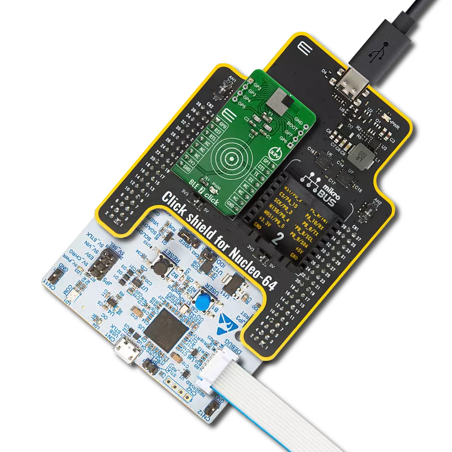
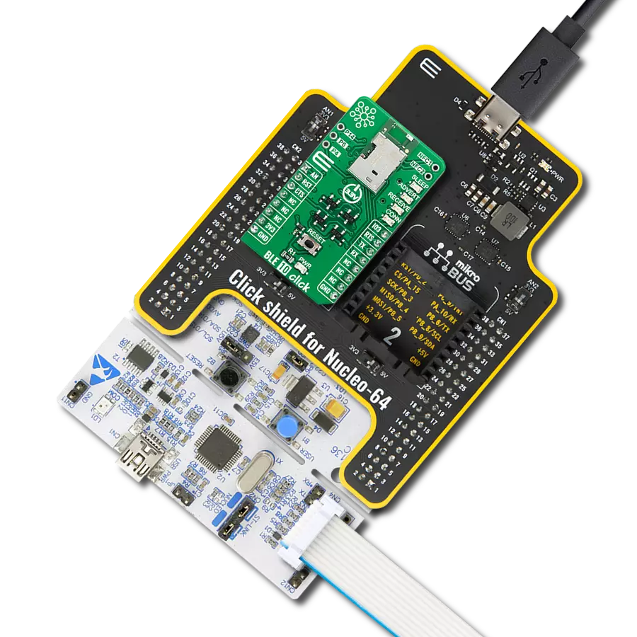
Start by selecting your development board and Click board™. Begin with the Curiosity Nano with PIC18F57Q43 as your development board.


Track your results in real time
Application Output
1. Application Output - In Debug mode, the 'Application Output' window enables real-time data monitoring, offering direct insight into execution results. Ensure proper data display by configuring the environment correctly using the provided tutorial.

2. UART Terminal - Use the UART Terminal to monitor data transmission via a USB to UART converter, allowing direct communication between the Click board™ and your development system. Configure the baud rate and other serial settings according to your project's requirements to ensure proper functionality. For step-by-step setup instructions, refer to the provided tutorial.

3. Plot Output - The Plot feature offers a powerful way to visualize real-time sensor data, enabling trend analysis, debugging, and comparison of multiple data points. To set it up correctly, follow the provided tutorial, which includes a step-by-step example of using the Plot feature to display Click board™ readings. To use the Plot feature in your code, use the function: plot(*insert_graph_name*, variable_name);. This is a general format, and it is up to the user to replace 'insert_graph_name' with the actual graph name and 'variable_name' with the parameter to be displayed.

Software Support
Library Description
This library contains API for NanoBeacon Click driver.
Key functions:
nanobeacon_set_advertising- This function sets the device MAC address, interval and advertising raw data.nanobeacon_load_adv_to_ram- This function loads advertising data to RAM.nanobeacon_start_advertising- This function starts the advertising.
Open Source
Code example
The complete application code and a ready-to-use project are available through the NECTO Studio Package Manager for direct installation in the NECTO Studio. The application code can also be found on the MIKROE GitHub account.
/*!
 * @file main.c
 * @brief NanoBeacon Click Example.
 *
 * # Description
 * This example demonstrates the use of NanoBeacon click board by setting
 * the Eddystone URI advertisement to click boards webpage.
 *
 * The demo application is composed of two sections :
 *
 * ## Application Init
 * Initializes the driver and logger.
 *
 * ## Application Task
 * Every 10 seconds, it restarts and configures the device for advertisement
 * with the Eddystone URI beacon format set to click boards webpage: https://www.mikroe.com/click
 *
 * @note
 * During advertising, the click board should appear as an Eddystone URI beacon on
 * the BLE Scanner application.
 *
 * @author Stefan Filipovic
 *
 */

#include "board.h"
#include "log.h"
#include "nanobeacon.h"

static nanobeacon_t nanobeacon;
static log_t logger;

void application_init ( void )
{
    log_cfg_t log_cfg;  /**< Logger config object. */
    nanobeacon_cfg_t nanobeacon_cfg;  /**< Click config object. */

    /**
     * Logger initialization.
     * Default baud rate: 115200
     * Default log level: LOG_LEVEL_DEBUG
     * @note If USB_UART_RX and USB_UART_TX
     * are defined as HAL_PIN_NC, you will
     * need to define them manually for log to work.
     * See @b LOG_MAP_USB_UART macro definition for detailed explanation.
     */
    LOG_MAP_USB_UART( log_cfg );
    log_init( &logger, &log_cfg );
    log_info( &logger, " Application Init " );

    // Click initialization.
    nanobeacon_cfg_setup( &nanobeacon_cfg );
    NANOBEACON_MAP_MIKROBUS( nanobeacon_cfg, MIKROBUS_1 );
    if ( UART_ERROR == nanobeacon_init( &nanobeacon, &nanobeacon_cfg ) )
    {
        log_error( &logger, " Communication init." );
        for ( ; ; );
    }

    log_info( &logger, " Application Task " );
}

void application_task ( void )
{
    // The device MAC address for advertisement
    static uint8_t mac_address[ 6 ] = { 0x01, 0x02, 0x03, 0x04, 0x05, 0x06 };

    // Eddystone advertisement raw data
    static uint8_t eddystone_adv_raw[ ] =
    {
        0x03, // Length of Service List
        0x03, // Param: Service List
        0xAA, 0xFE, // Eddystone ID
        0x12, // Length of Service Data
        0x16, // Service Data
        0xAA, 0xFE, // Eddystone ID
        0x10, // Frame type: URL
        0x00, // Power
        0x01, // https://www.
        'm','i','k','r','o','e',
        0x00, // .com/
        'c','l','i','c','k'
    };
    log_printf( &logger, "\r\n Restart device\r\n" );
    nanobeacon_restart_device ( &nanobeacon );

    while ( NANOBEACON_OK != nanobeacon_check_communication ( &nanobeacon ) )
    {
        log_error( &logger, " Check communication." );
        Delay_ms ( 1000 );
    }
    log_printf( &logger, " Configure device for advertisement\r\n" );
    if ( NANOBEACON_OK != nanobeacon_set_advertising ( mac_address, 1000, eddystone_adv_raw,
                                                       sizeof( eddystone_adv_raw ) ) )
    {
        log_error( &logger, " Set advertising." );
    }

    if ( NANOBEACON_OK != nanobeacon_load_adv_to_ram( &nanobeacon ) )
    {
        log_error( &logger, " Load data to RAM." );
    }

    log_printf( &logger, " Start advertising\r\n" );
    if ( NANOBEACON_OK != nanobeacon_start_advertising ( &nanobeacon ) )
    {
        log_error( &logger, " Start advertising." );
    }
    Delay_ms ( 10000 );
}

void main ( void )
{
    application_init( );

    for ( ; ; )
    {
        application_task( );
    }
}

// ------------------------------------------------------------------------ END