Enable seamless integration of smart lighting controls with TPS54200 and PIC32MZ2048EFM100
Lighting innovation at your fingertips
Published Sep 05, 2023
Click board™
LED Driver 5 Click
Dev. board
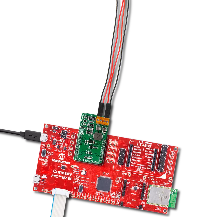
Curiosity PIC32 MZ EF
Compiler
NECTO Studio
MCU
PIC32MZ2048EFM100
Ensure consistent and stable LED illumination in your electronic products, thanks to our precision LED driver technology
A
A
Hardware Overview
How does it work?
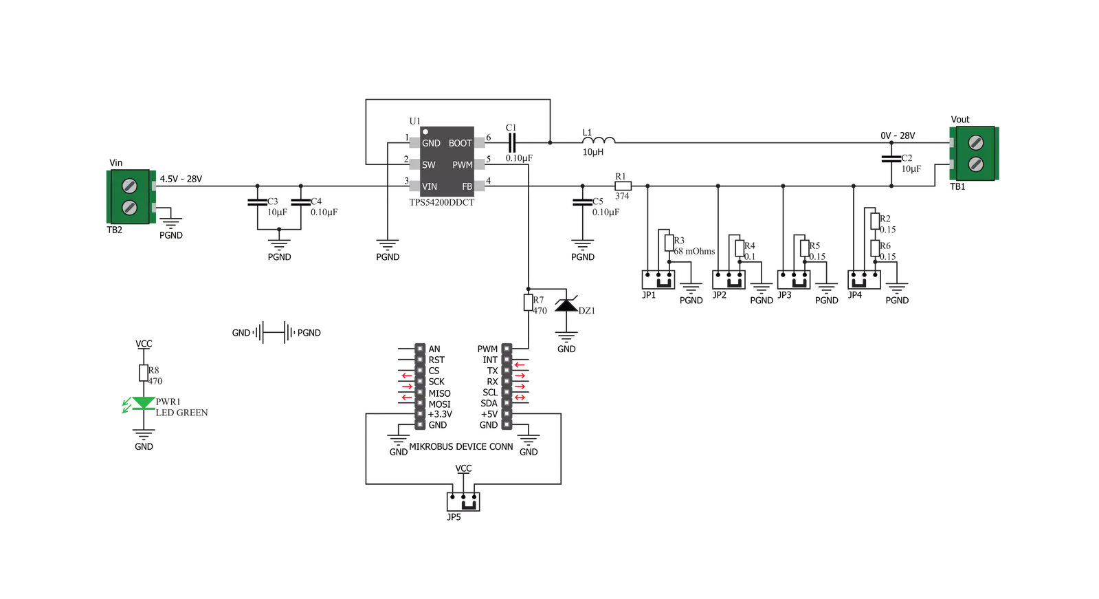
LED Driver 5 Click is based on the TPS54200, a synchronous buck converter designed to drive monochrome, color, and IR LED arrays made by Texas Instruments. The Click board™ is very flexible regarding the input voltage choice, allowing any voltage from 4.5V up to 28V. This is possible thanks to the TPS54200 driver IC, which integrates a buck converter IC and supports LED dimming by using the pulse width of the PWM signal on the control input. This IC has a mode selection logic circuitry used to select one of two dimming modes, depending on the incoming PWM control signal level. The PWM pin is used to control more than just one function. Besides choosing the dimming mode (analog or PWM), this pin is also used to turn the IC on or off. If the signal at the PWM pin rises above the threshold value (0.56V typically), the IC will be enabled. Keeping the voltage at the PWM pin lower than 0.56V for at least 40 ms will disable the IC. After the device is enabled, the magnitude of the PWM signal is detected and stored by an internal peak detector. The voltage of the peak detector is then compared with two threshold values, VADIM and VPDIM, after 300 µs. If the peak detector output exceeds 2.07V, analog dimming mode will be selected and locked. If the peak detector voltage ranges between 1V and 2.07V, the PWM dimming mode will be selected and locked. If the voltage is less than 1V, the detection process will be repeated
after 300 µs until one of two operating modes is selected and locked. Once locked, the dimming mode can only be changed by cycling the VIN voltage or re-enabling the IC. The PWM pin is routed to the PWM pin of the mikroBUS™, allowing it to be controlled by the host microcontroller (MCU). When the analog dimming mode is selected (the magnitude of the control PWM signal is above 2.06V during the boot-up sequence of the TPS54200), the internal reference voltage (VREF) is scaled down according to the duty cycle of the PWM signal applied to the PWM pin. The internal reference voltage for this mode is 200 mV at full scale (duty-cycle at 100%). As the duty cycle decreases, the reference voltage is scaled down to 1% of its value. This will also cause the current through the LED to be scaled, effectively dimming the LED. This type of dimming, where the LED intensity is dimmed to a low level invisible to the eye, is sometimes called deep-dimming. The PWM control signal at the PWM pin should stay within the range of 10 kHz to reduce the output voltage ripple. If the PWM dimming mode is selected (the magnitude of the control PWM signal is between 1V and 2.06V during the boot-up sequence of the TPS54200), the internal reference voltage is fixed at 100mA. In this mode, the LED dimming is performed using the PWM signal applied to the PWM pin, modulating the LED output. Holding the
internal reference voltage fixed, the LED at the output will only be switched ON or OFF, according to the duty cycle of the control PWM signal. The buck converter itself is a very feature-rich circuitry, a synchronous buck converter, operating at the fixed frequency of 600kHz. This offers an excellent size/efficiency ratio, keeping the footprint of the TPS54200 IC very small. Features such as the open LED or shorted LED detection, overvoltage and under-voltage protection, over-current and open loop protection, thermal shutdown, and soft start function that prevents the inrush current allow the Click board™ to be a very reliable and safe solution for driving high current LEDs or LED arrays. The Click board™ contains four SMD jumpers used to select the current through the LED array. They are grouped and labeled as IOUT. There are four settings: 0.35A, 0.7A, 1A, and 1.5A. Switching the current selection SMD jumper to the ON position will connect a respective sensing resistor (RS)to the circuit. Switching two SMD jumpers to the ON position simultaneously will cause them to form a parallel connection with their equivalent resistance. However, this is not recommended since almost all the resistor combinations will result in a value too low to be used (the LED current will be above 1.5A, thus triggering the protection circuit).

Features overview
Development board
Curiosity PIC32 MZ EF development board is a fully integrated 32-bit development platform featuring the high-performance PIC32MZ EF Series (PIC32MZ2048EFM) that has a 2MB Flash, 512KB RAM, integrated FPU, Crypto accelerator, and excellent connectivity options. It includes an integrated programmer and debugger, requiring no additional hardware. Users can expand
functionality through MIKROE mikroBUS™ Click™ adapter boards, add Ethernet connectivity with the Microchip PHY daughter board, add WiFi connectivity capability using the Microchip expansions boards, and add audio input and output capability with Microchip audio daughter boards. These boards are fully integrated into PIC32’s powerful software framework, MPLAB Harmony,
which provides a flexible and modular interface to application development a rich set of inter-operable software stacks (TCP-IP, USB), and easy-to-use features. The Curiosity PIC32 MZ EF development board offers expansion capabilities making it an excellent choice for a rapid prototyping board in Connectivity, IOT, and general-purpose applications.

Microcontroller Overview
MCU Card / MCU

Architecture
PIC32
MCU Memory (KB)
2048
Silicon Vendor
Microchip
Pin count
100
RAM (Bytes)
524288
Used MCU Pins
mikroBUS™ mapper
Take a closer look
Click board™ Schematic
Step by step
Project assembly

Start by selecting your development board and Click board™. Begin with the Curiosity PIC32 MZ EF as your development board.


Software Support
Library Description
This library contains API for LED Driver 5 Click driver.
Key functions:
leddriver5_set_duty_cycle- Generic sets PWM duty cycleleddriver5_pwm_stop- Stop PWM moduleleddriver5_pwm_start- Start PWM module
Open Source
Code example
The complete application code and a ready-to-use project are available through the NECTO Studio Package Manager for direct installation in the NECTO Studio. The application code can also be found on the MIKROE GitHub account.
/*!
 * @file
 * @brief LedDriver5 Click example
 *
 * # Description
 * The application is a capable of driving an array of high-power LEDs.
 *
 * The demo application is composed of two sections :
 *
 * ## Application Init
 * Initialization driver init and pwm init
 *
 * ## Application Task
 * This is an example that demonstrates the use of the LED Driver 5 Click board.
 * This example shows the automatic control of Led light intensity,
 * the first intensity of light is rising and then the intensity of light is falling.
 * Results are being sent to the Usart Terminal where you can track their changes.
 *
 *
 * @author Nikola Peric
 *
 */
// ------------------------------------------------------------------- INCLUDES

#include "board.h"
#include "log.h"
#include "leddriver5.h"

// ------------------------------------------------------------------ VARIABLES

static leddriver5_t leddriver5;
static log_t logger;

// ------------------------------------------------------ APPLICATION FUNCTIONS

void application_init ( void )
{
    log_cfg_t log_cfg;
    leddriver5_cfg_t cfg;

    /**
     * Logger initialization.
     * Default baud rate: 115200
     * Default log level: LOG_LEVEL_DEBUG
     * @note If USB_UART_RX and USB_UART_TX
     * are defined as HAL_PIN_NC, you will
     * need to define them manually for log to work.
     * See @b LOG_MAP_USB_UART macro definition for detailed explanation.
     */
    LOG_MAP_USB_UART( log_cfg );
    log_init( &logger, &log_cfg );
    log_info( &logger, "---- Application Init ----" );

    //  Click initialization.

    leddriver5_cfg_setup( &cfg );
    LEDDRIVER5_MAP_MIKROBUS( cfg, MIKROBUS_1 );
    leddriver5_init( &leddriver5, &cfg );

    leddriver5_pwm_start( &leddriver5 );
}

void application_task ( void )
{
    static int8_t duty_cnt = 1;
    static int8_t duty_inc = 1;
    float duty = duty_cnt / 10.0;

    leddriver5_set_duty_cycle( &leddriver5, duty );
    log_printf( &logger, "> Duty: %d%%\r\n", ( uint16_t )( duty_cnt * 10 ) );

    Delay_ms ( 500 );

    if ( 10 == duty_cnt )
    {
        duty_inc = -1;
    }
    else if ( 0 == duty_cnt )
    {
        duty_inc = 1;
    }
    duty_cnt += duty_inc;
}

int main ( void )
{
    /* Do not remove this line or clock might not be set correctly. */
    #ifdef PREINIT_SUPPORTED
    preinit();
    #endif

    application_init( );

    for ( ; ; )
    {
        application_task( );
    }

    return 0;
}


// ------------------------------------------------------------------------ END
Additional Support
Resources
Category:LED Drivers


