Measure currents with the greatest precision using EMC1702 and PIC18LF46K80
Your journey to next-level measurement and insights
Published Nov 01, 2023
Click board™
Current 3 Click
Dev. board
EasyPIC v8
Compiler
NECTO Studio
MCU
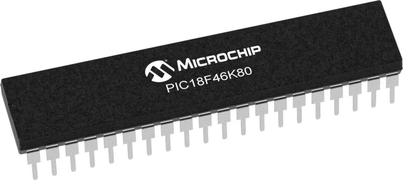
PIC18LF46K80
Elevate safety and compliance in your operations with our current measurement solution, which facilitates accurate current monitoring, ensuring adherence to industry standards and regulations
A
A
Hardware Overview
How does it work?
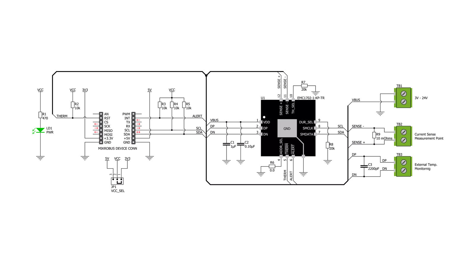
Current 3 Click is based on the EMC1702, a combination of the high-side current sensing device with precision voltage and temperature measurement capabilities from Microchip. It measures the voltage developed across an external sense resistor to represent the high-side current of a battery or voltage regulator. It also measures the source voltage and uses these measured values to present a proportional power calculation. The EMC1702 contains additional bi-directional peak detection circuitry to flag instantaneous current spikes with programmable time duration and magnitude threshold. Also, it possesses an external diode channel for temperature measurement and an internal diode for ambient temperature measurements. The EMC1702 current-sense measurement converts differential input voltage measured across an
external sense resistor to a proportional output voltage. This voltage is digitized using a variable resolution (13-bit to 15-bit) Sigma-Delta ADC and I2C protocol. The current range allows for large variations in measured current with high accuracy and a low voltage drop across the resistor. Current 3 Click communicates with MCU using the standard I2C 2-Wire interface with a maximum frequency of 400kHz. The EMC1702 slave address is determined by a resistor connected R6 (0Ω) between the ground and the ADDR_SEL pin. Various values of this resistor also provide different slave addresses (0Ω is equal to 1001_100(r/w)). The EMC1702 has two levels of monitoring and contains user-programmable bipolar Full-Scale Sense Ranges (FSSR). Each VSENSE measurement is averaged over a user-programmable time. If VSENSE exceeds (or drops below) the respective
limits, the ALERT pin, routed on the INT pin of the mikroBUS™ socket labeled as ALT, may be asserted. It also contains user-programmable current peak detection circuitry on DUR_SEL and TH_SEL pins that will assert the THERM pin, routed on the RST pin of the mikroBUS™ socket labeled as TRM, if a current spike is detected larger than the programmed threshold and of longer duration than the programmed time (threshold and duration selected by resistors R7 and R8). This Click board™ can operate with either 3.3V or 5V logic voltage levels selected via the VCC SEL jumper. This way, both 3.3V and 5V capable MCUs can use the communication lines properly. Also, this Click board™ comes equipped with a library containing easy-to-use functions and an example code that can be used, as a reference, for further development.

Features overview
Development board
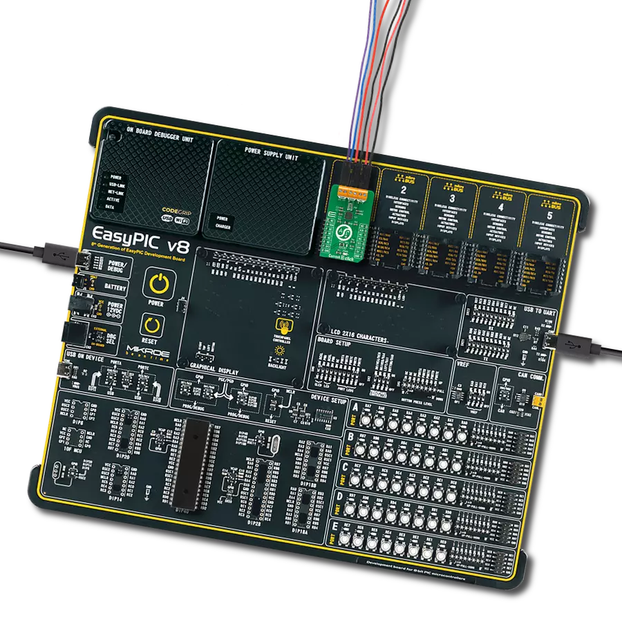
EasyPIC v8 is a development board specially designed for the needs of rapid development of embedded applications. It supports many high pin count 8-bit PIC microcontrollers from Microchip, regardless of their number of pins, and a broad set of unique functions, such as the first-ever embedded debugger/programmer. The development board is well organized and designed so that the end-user has all the necessary elements, such as switches, buttons, indicators, connectors, and others, in one place. Thanks to innovative manufacturing technology, EasyPIC v8 provides a fluid and immersive working experience, allowing access anywhere and under any
circumstances at any time. Each part of the EasyPIC v8 development board contains the components necessary for the most efficient operation of the same board. In addition to the advanced integrated CODEGRIP programmer/debugger module, which offers many valuable programming/debugging options and seamless integration with the Mikroe software environment, the board also includes a clean and regulated power supply module for the development board. It can use a wide range of external power sources, including a battery, an external 12V power supply, and a power source via the USB Type-C (USB-C) connector.
Communication options such as USB-UART, USB DEVICE, and CAN are also included, including the well-established mikroBUS™ standard, two display options (graphical and character-based LCD), and several different DIP sockets. These sockets cover a wide range of 8-bit PIC MCUs, from the smallest PIC MCU devices with only eight up to forty pins. EasyPIC v8 is an integral part of the Mikroe ecosystem for rapid development. Natively supported by Mikroe software tools, it covers many aspects of prototyping and development thanks to a considerable number of different Click boards™ (over a thousand boards), the number of which is growing every day.

Microcontroller Overview
MCU Card / MCU
Architecture
PIC
MCU Memory (KB)
64
Silicon Vendor
Microchip
Pin count
40
RAM (Bytes)
3648
Used MCU Pins
mikroBUS™ mapper
Take a closer look
Click board™ Schematic
Step by step
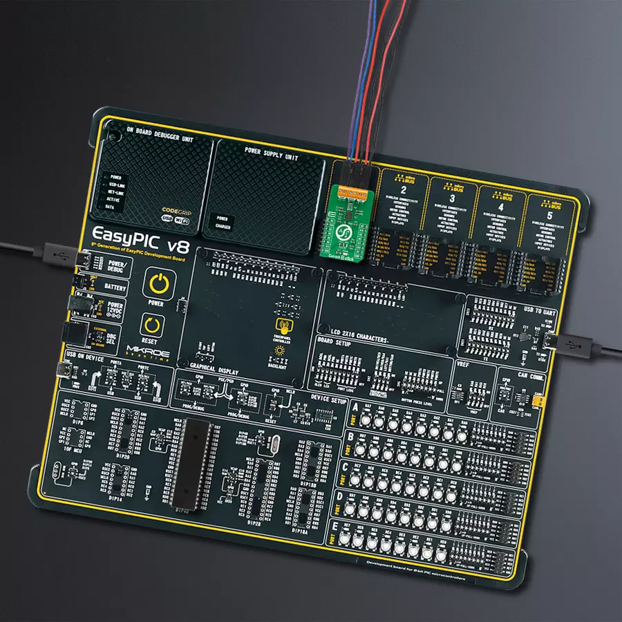
Project assembly

Start by selecting your development board and Click board™. Begin with the EasyPIC v8 as your development board.


Software Support
Library Description
This library contains API for Current 3 Click driver.
Key functions:
current3_get_temperature- The function get the temperature by read multiple data bytes from a group of contiguous registerscurrent3_get_source_voltage- The function source voltage registers store the voltage measured at the SENSE+ pincurrent3_get_current- The function current measurement measure the direction of current flow ( from SENSE+ to SENSE- or from SENSE- to SENSE+ )
Open Source
Code example
The complete application code and a ready-to-use project are available through the NECTO Studio Package Manager for direct installation in the NECTO Studio. The application code can also be found on the MIKROE GitHub account.
/*!
* \file
* \brief Current3 Click example
*
* # Description
* Current 3 Click can be used to measure current ranging up to 8000mA, and display temperature,
* voltage and current data - using I2C comunication.
*
* The demo application is composed of two sections :
*
* ## Application Init
* Initialization driver enables - I2C,
* check communication and set sense sampling configuration, also write log.
*
* ## Application Task
* This is an example which demonstrates the use of Current 3 Click board.
* Current 3 Click board can be used to measure current ranging
* up to 8000mA, and display temperature, voltage and current data.
* All data logs write on USB uart changes for every 2 sec.
*
*
* \author MikroE Team
*
*/
// ------------------------------------------------------------------- INCLUDES
#include "board.h"
#include "log.h"
#include "current3.h"
// ------------------------------------------------------------------ VARIABLES
static current3_t current3;
static log_t logger;
static current3_sense_cfg_data_t sense_cfg_data;
static float temperature;
static float voltage;
static float current;
// ------------------------------------------------------ APPLICATION FUNCTIONS
void application_init ( void )
{
log_cfg_t log_cfg;
current3_cfg_t cfg;
uint8_t read_data;
/**
* Logger initialization.
* Default baud rate: 115200
* Default log level: LOG_LEVEL_DEBUG
* @note If USB_UART_RX and USB_UART_TX
* are defined as HAL_PIN_NC, you will
* need to define them manually for log to work.
* See @b LOG_MAP_USB_UART macro definition for detailed explanation.
*/
LOG_MAP_USB_UART( log_cfg );
log_init( &logger, &log_cfg );
log_info( &logger, "---- Application Init ----" );
// Click initialization.
current3_cfg_setup( &cfg );
CURRENT3_MAP_MIKROBUS( cfg, MIKROBUS_1 );
current3_init( ¤t3, &cfg );
Delay_ms ( 100 );
log_printf( &logger, " Driver init. done \r\n" );
log_printf( &logger, "---------------------------\r\n" );
current3_generic_read( ¤t3, CURRENT3_REG_PRODUCT_ID, &read_data, 1 );
if ( read_data == CURRENT3_DEV_ID )
{
log_printf( &logger, " Communication OK \r\n" );
log_printf( &logger, "---------------------------\r\n" );
}
else
{
log_printf( &logger, " Communication ERROR \r\n" );
log_printf( &logger, " Reset the device \r\n" );
log_printf( &logger, "---------------------------\r\n" );
for ( ; ; );
}
current3_default_cfg( ¤t3, sense_cfg_data );
}
void application_task ( void )
{
temperature = current3_get_temperature( ¤t3, CURRENT3_TEMP_INTERNAL_DIODE );
log_printf( &logger, " Temperature = %.2f C\r\n", temperature );
voltage = current3_get_source_voltage( ¤t3 );
log_printf( &logger, " Voltage = %.2f V\r\n", voltage );
current = current3_get_current( ¤t3 );
log_printf( &logger, " Current = %.2f mA\r\n", current );
log_printf( &logger, "---------------------------\r\n" );
Delay_ms ( 1000 );
Delay_ms ( 1000 );
}
int main ( void )
{
/* Do not remove this line or clock might not be set correctly. */
#ifdef PREINIT_SUPPORTED
preinit();
#endif
application_init( );
for ( ; ; )
{
application_task( );
}
return 0;
}
// ------------------------------------------------------------------------ END


