Achieve unparalleled precision in sensing both magnetic and gravitational fields using LSM303AGR and PIC18F47K42
Your window into magnetic and gravitational fields

Published Sep 13, 2023
Click board™
LSM303AGR Click
Dev. board
EasyPIC v8
Compiler
NECTO Studio
MCU
PIC18F47K42
Our innovative solution opens the door to a new era of sensing capabilities, allowing you to precisely measure the magnetic and gravitational fields along three orthogonal axes. It's your key to unlocking groundbreaking insights in geophysics, navigation, and beyond.
A
A
Hardware Overview
How does it work?
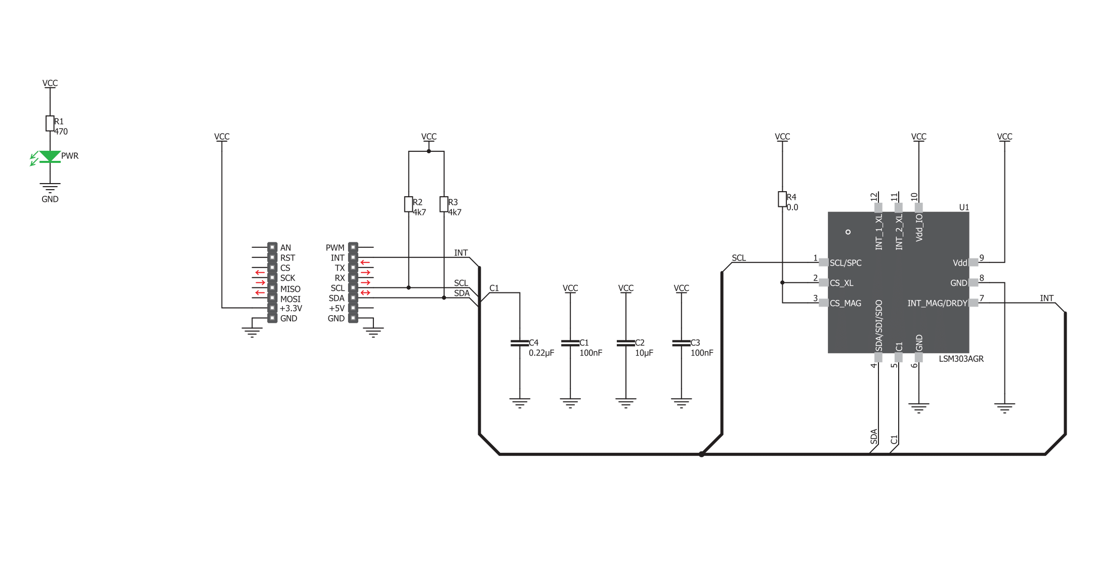
LSM303AGR Click is based on the LSM303AGR, a low-power and high-performance sensor featuring a digital linear acceleration sensor, and a digital magnetic sensor from STMicroelectronics, capable of sensing magnetic and gravitational fields in all three axes. The sensor is a highly integrated system in package (SIP), offering two independent sensors, charge amplifiers, A/D converters, and control logic sections. There are two independent I2C slave addresses for each of the sensors: 0011001b is the slave address of the accelerometer, while the 0011110b is the slave address of the magnetic sensor. These are 7bit addresses, to complete the address sequence, an R/W bit needs to be added at the end. An interrupt pin (INT_MAG/DRDY) allows the interrupt generated by an event within the LSM303AGR IC, to alert the host MCU. This pin is routed to the mikroBUS™ INT pin. The power of the LSM303AGR IC lies in its configurable interrupt engine. The function, threshold, and timing of the interrupt signal on the INT pin can be completely defined by the user. Its behavior can be programmed by setting a range of appropriate registers via the I2C bus. The sensor offers detection of many events, caused either by the sensors themselves or by the error/status events within the sensor IC. For example, the interrupt can be generated if there is data ready to be transferred to the host MCU if the FIFO buffer overflow occurred and so on.
A combination of events is also available, with either 'OR' or 'AND' function between the generated events. It allows developing HID applications, which react on tapping, moving, positioning, etc. The LSM303AGR device offers digital filtering, compensation, self-test, and more. It allows resolution, sampling time and power consumption to be adjusted, allowing the Click board™ to be tailored to any application. Trimming values for zero-g level, zero-gauss level, and sensitivity adjustment are stored into the internal non-volatile memory and are copied to the registers upon restart. This allows the sensor to perform accurate measurements without repeated calibration after each power-up cycle. Another feature used to increase the accuracy of the sensor is the hard-iron compensation, which compensates the readings, in cases when an object with magnetic properties is placed near the sensor, permanently biasing the output values. Six registers hold magnetic values for the compensation and are automatically subtracted from readings. Many signal processing features such as the low-pass and high-pass filtering, also help to obtain accurate and reliable readings from this sensor. A self-test procedure can be used to verify the functionality of the device. The internal current generates an internal magnetic field, which is then sensed by the sensors. The readings during self-test should look like in the table,
given in the LSM303AGR datasheet. If these readings look differently, a particular device can be discarded. The device contains a FIFO buffer, which can be used for the accelerometer sensor only. It is 32 levels deep, allowing 32 sets of readings along X, Y, and Z axes to be stored. The buffer can be bypassed, it can be fixed so that new data is discarded when it is full, and it can be set to streaming mode so that the new data pushes out the oldest information from the buffer. An interrupt can be triggered if a programmed threshold is exceeded so that the buffer can be read before the data is lost. The sampling frequency and the resolution can be selected from 1Hz up to 5.736 kHz and from 8 bits up to 12 bits. These settings affect the power consumption. The device can work in normal mode, high-resolution mode, and low power mode. This affects the acquisition time as well as the power consumption. In addition, the device can work in continuous mode, or in a single shot mode. A single shot mode allows the device to consume less power, as the single measurement is done on a command, after which device reverts to idle mode and the DRDY (data ready) bit is set. Again, the datasheet of the LSM303AGR offers an in-depth explanation of all the registers and their functionality.


Features overview
Development board
EasyPIC v8 is a development board specially designed for the needs of rapid development of embedded applications. It supports many high pin count 8-bit PIC microcontrollers from Microchip, regardless of their number of pins, and a broad set of unique functions, such as the first-ever embedded debugger/programmer. The development board is well organized and designed so that the end-user has all the necessary elements, such as switches, buttons, indicators, connectors, and others, in one place. Thanks to innovative manufacturing technology, EasyPIC v8 provides a fluid and immersive working experience, allowing access anywhere and under any
circumstances at any time. Each part of the EasyPIC v8 development board contains the components necessary for the most efficient operation of the same board. In addition to the advanced integrated CODEGRIP programmer/debugger module, which offers many valuable programming/debugging options and seamless integration with the Mikroe software environment, the board also includes a clean and regulated power supply module for the development board. It can use a wide range of external power sources, including a battery, an external 12V power supply, and a power source via the USB Type-C (USB-C) connector.
Communication options such as USB-UART, USB DEVICE, and CAN are also included, including the well-established mikroBUS™ standard, two display options (graphical and character-based LCD), and several different DIP sockets. These sockets cover a wide range of 8-bit PIC MCUs, from the smallest PIC MCU devices with only eight up to forty pins. EasyPIC v8 is an integral part of the Mikroe ecosystem for rapid development. Natively supported by Mikroe software tools, it covers many aspects of prototyping and development thanks to a considerable number of different Click boards™ (over a thousand boards), the number of which is growing every day.

Microcontroller Overview
MCU Card / MCU
Architecture
PIC
MCU Memory (KB)
128
Silicon Vendor
Microchip
Pin count
40
RAM (Bytes)
8192
Used MCU Pins
mikroBUS™ mapper
Take a closer look
Click board™ Schematic
Step by step
Project assembly

Start by selecting your development board and Click board™. Begin with the EasyPIC v8 as your development board.


Software Support
Library Description
This library contains API for LSM303AGR Click driver.
Key functions:
lsm303agr_get_acc_axis_x- Reading the raw X axis data and calculating the valuelsm303agr_get_mag_axis_x- Reading the raw X axis data and calculating the valuelsm303agr_get_mag_axis_y- Reading the raw Y axis data and calculating the value
Open Source
Code example
The complete application code and a ready-to-use project are available through the NECTO Studio Package Manager for direct installation in the NECTO Studio. The application code can also be found on the MIKROE GitHub account.
/*!
 * \file
 * \brief LSM303AGR Click example
 *
 * # Description
 * This example returns accel and magnet values from the LSM303AGR sensor.
 *
 * The demo application is composed of two sections :
 *
 * ## Application Init
 * I2C Driver initaliation and setting operating modes of accelerometer and
 * magnetometer
 *
 * ## Application Task
 * Reading accelerometer and magnetometer axis X,Y,Z and displaying via UART
 *
 *
 * \author MikroE Team
 *
 */
// ------------------------------------------------------------------- INCLUDES

#include "board.h"
#include "log.h"
#include "lsm303agr.h"

// ------------------------------------------------------------------ VARIABLES

static lsm303agr_t lsm303agr;
static log_t logger;
static float read_data;

// ------------------------------------------------------ APPLICATION FUNCTIONS

void application_init ( void )
{
    log_cfg_t log_cfg;
    lsm303agr_cfg_t cfg;

    /**
     * Logger initialization.
     * Default baud rate: 115200
     * Default log level: LOG_LEVEL_DEBUG
     * @note If USB_UART_RX and USB_UART_TX
     * are defined as HAL_PIN_NC, you will
     * need to define them manually for log to work.
     * See @b LOG_MAP_USB_UART macro definition for detailed explanation.
     */
    LOG_MAP_USB_UART( log_cfg );
    log_init( &logger, &log_cfg );
    log_info( &logger, "---- Application Init ----" );

    //  Click initialization.

    lsm303agr_cfg_setup( &cfg );
    LSM303AGR_MAP_MIKROBUS( cfg, MIKROBUS_1 );
    lsm303agr_init( &lsm303agr, &cfg );

    lsm303agr_default_cfg ( &lsm303agr );

}

void application_task ( void )
{
    //  Task implementation.

    log_printf(&logger, "======== Accelerometer data ========\r\n");

    read_data = lsm303agr_get_acc_axis_x ( &lsm303agr );
    log_printf(&logger, "X Axis : %.2f\r\n", read_data);

    read_data = lsm303agr_get_acc_axis_y ( &lsm303agr );
    log_printf(&logger, "Y Axis : %.2f\r\n", read_data);

    read_data = lsm303agr_get_acc_axis_z ( &lsm303agr );
    log_printf(&logger, "Z Axis : %.2f\r\n", read_data);

    log_printf(&logger, "======== Mangetometer data ========\r\n");

    read_data = lsm303agr_get_mag_axis_x ( &lsm303agr );
    log_printf(&logger, "X Axis : %.2f\r\n", read_data);

    read_data = lsm303agr_get_mag_axis_y ( &lsm303agr );
    log_printf(&logger, "Y Axis : %.2f\r\n", read_data);

    read_data = lsm303agr_get_mag_axis_z ( &lsm303agr );
    log_printf(&logger, "Z Axis : %.2f\r\n", read_data);

    Delay_ms ( 1000 );
    Delay_ms ( 1000 );
}

int main ( void )
{
    /* Do not remove this line or clock might not be set correctly. */
    #ifdef PREINIT_SUPPORTED
    preinit();
    #endif

    application_init( );

    for ( ; ; )
    {
        application_task( );
    }

    return 0;
}


// ------------------------------------------------------------------------ END


