Step confidently into the future of power management with MAX17624 and PIC18F46K22
Transform power with precision using our step-down DC-DC wizardry
Published Nov 12, 2023
Click board™
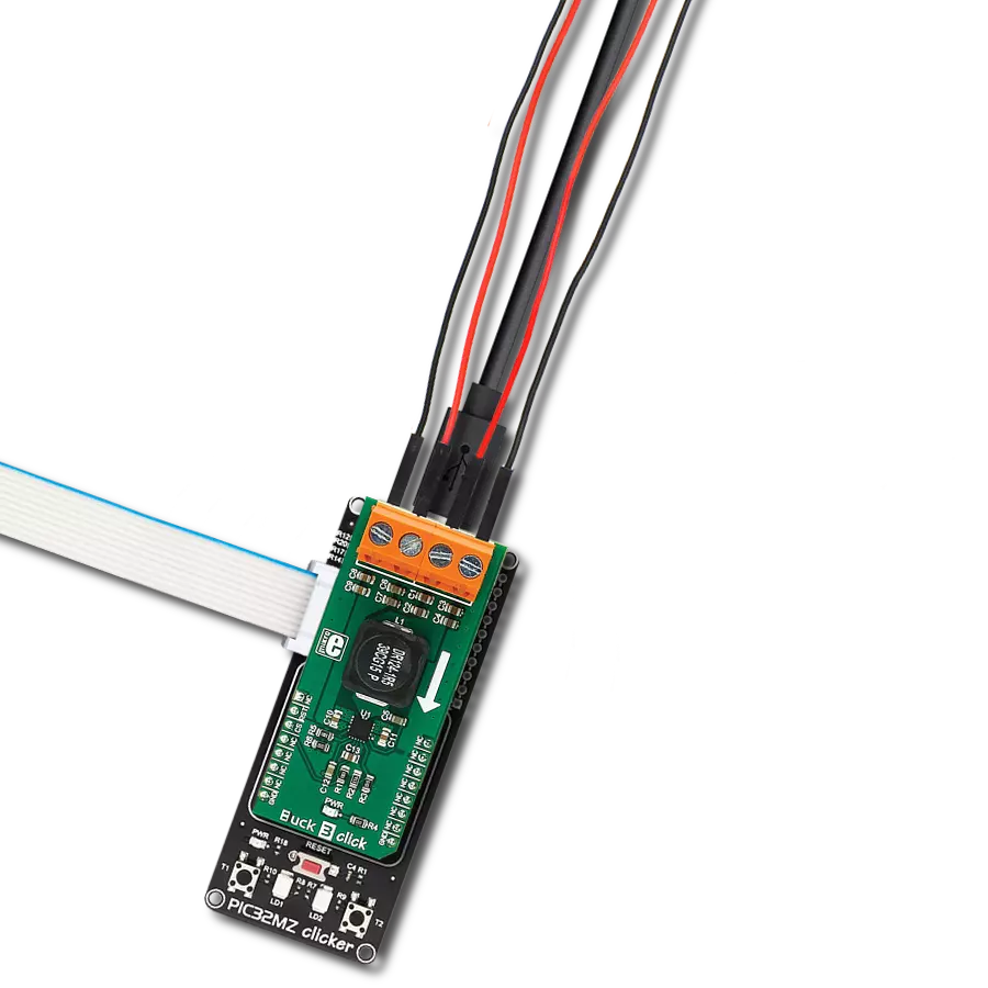
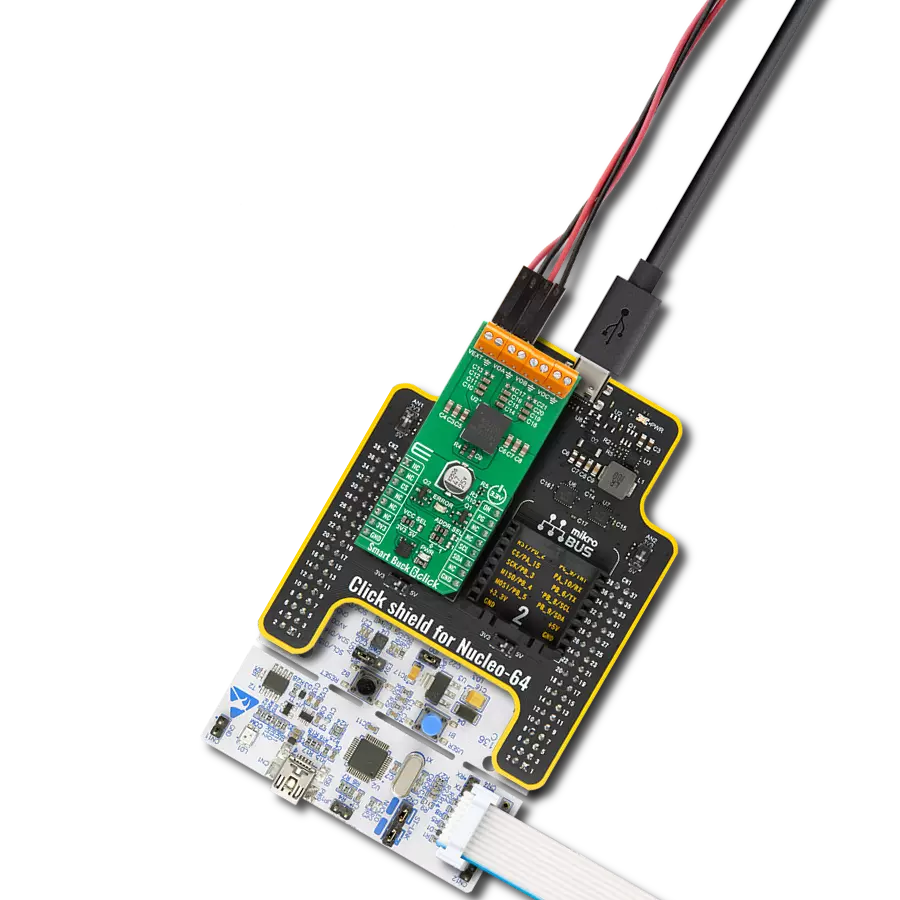
Step Down 7 Click
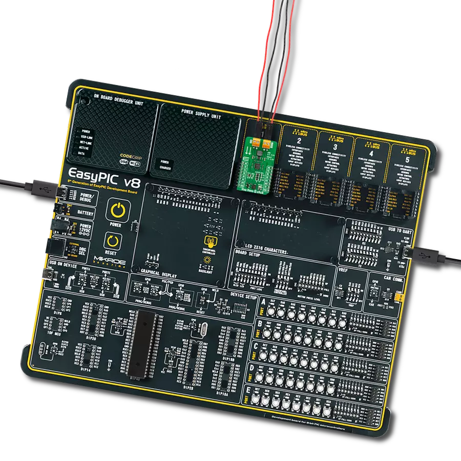
Dev. board
EasyPIC v8
Compiler
NECTO Studio
MCU
PIC18F46K22
Our synchronous step-down DC-DC converter stands as a pinnacle of power efficiency, offering precise voltage regulation and current control to meet the demands of your electronic applications.
A
A
Hardware Overview
How does it work?
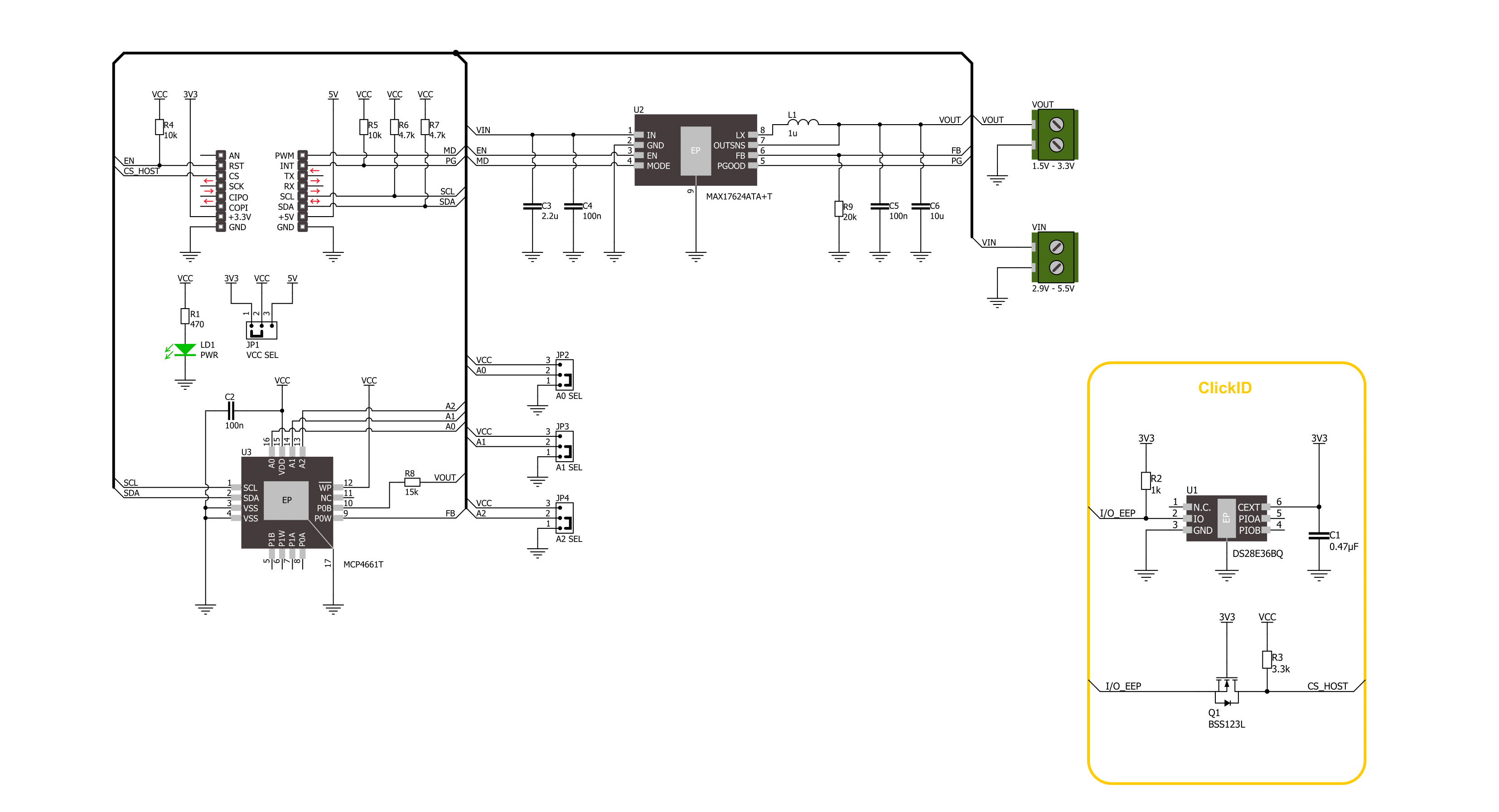
Step Down 7 Click is based on the MAX17624, a synchronous step-down converter with integrated MOSFETs from Analog Devices. The converter uses soft start ramp technology, allowing a smooth output voltage increase. The output voltage is monitored through a resistor divider as feedback. On this Click board™, the resistor divider consists of a resistor and the MCP4661T, an 8-bit dual digital POT with volatile memory from Microchip. This 50K digital potentiometer has a resistor ladder with ends connected to the analog switches and terminals A and B. The 256 resistors give 257 wiper positions. The potentiometer features high-speed read/write to the wiper and increment/decrement of wiper serial protocols. The MAX17624 has two selectable modes of operation, the PWM and the PFM modes. The PWM mode is used in fixed-frequency operations
with a fixed 4MHz switching frequency. This mode allows the device’s output current to go negative and is useful in frequency-sensitive applications as it provides fixed switching frequency operations at all loads. The PWM mode gives lower efficiency at light loads compared to a PFM mode of operation. The PFM mode disables the negative output current from the device, and skips pulse at light loads for better efficiency. Another feature of the step-down converter is Power Good, which indicates the output voltage status. Step Down 7 Click uses I/O pins to communicate with the host MCU. To change to the desired mode, you can set a logic state of the MD pin LOW for the PWM mode of operation; otherwise, the PFM mode is selected. Power Good output can be monitored over the PG pin. With the enabled EN pin, the MAX17624 will first go into soft start mode and,
after 1ms, will smoothly increase the voltage. The feedback is provided over the resistor divider and the digital potentiometer, which uses a standard 2-Wire I2C interface to communicate with the host MCU, supporting frequencies of 100KHz, 400KHz, and 3.4MHz. The I2C address can be selected over the combination of the three jumpers, with all of them set to 0 by default. This Click board™ can operate with either 3.3V or 5V logic voltage levels selected via the VCC SEL jumper. This way, both 3.3V and 5V capable MCUs can use the communication lines properly. Also, this Click board™ comes equipped with a library containing easy-to-use functions and an example code that can be used as a reference for further development.

Features overview
Development board
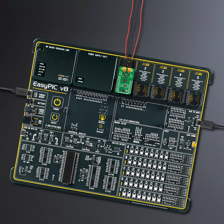
EasyPIC v8 is a development board specially designed for the needs of rapid development of embedded applications. It supports many high pin count 8-bit PIC microcontrollers from Microchip, regardless of their number of pins, and a broad set of unique functions, such as the first-ever embedded debugger/programmer. The development board is well organized and designed so that the end-user has all the necessary elements, such as switches, buttons, indicators, connectors, and others, in one place. Thanks to innovative manufacturing technology, EasyPIC v8 provides a fluid and immersive working experience, allowing access anywhere and under any
circumstances at any time. Each part of the EasyPIC v8 development board contains the components necessary for the most efficient operation of the same board. In addition to the advanced integrated CODEGRIP programmer/debugger module, which offers many valuable programming/debugging options and seamless integration with the Mikroe software environment, the board also includes a clean and regulated power supply module for the development board. It can use a wide range of external power sources, including a battery, an external 12V power supply, and a power source via the USB Type-C (USB-C) connector.
Communication options such as USB-UART, USB DEVICE, and CAN are also included, including the well-established mikroBUS™ standard, two display options (graphical and character-based LCD), and several different DIP sockets. These sockets cover a wide range of 8-bit PIC MCUs, from the smallest PIC MCU devices with only eight up to forty pins. EasyPIC v8 is an integral part of the Mikroe ecosystem for rapid development. Natively supported by Mikroe software tools, it covers many aspects of prototyping and development thanks to a considerable number of different Click boards™ (over a thousand boards), the number of which is growing every day.

Microcontroller Overview
MCU Card / MCU
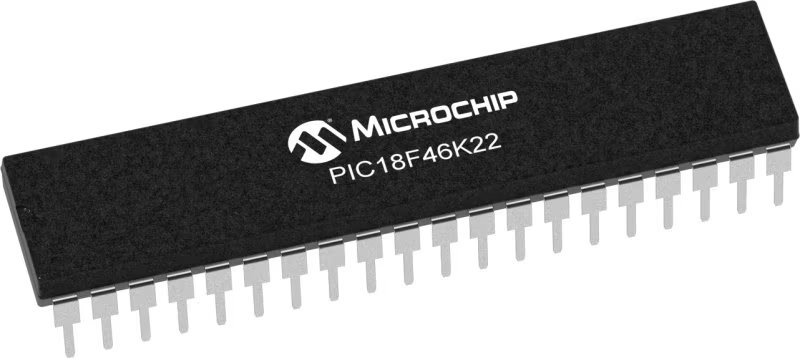
Architecture
PIC
MCU Memory (KB)
64
Silicon Vendor
Microchip
Pin count
40
RAM (Bytes)
3896
Used MCU Pins
mikroBUS™ mapper
Take a closer look
Click board™ Schematic
Step by step
Project assembly

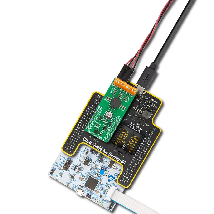
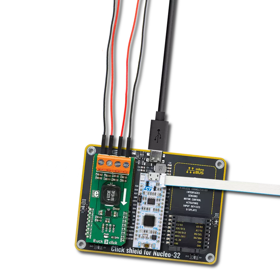
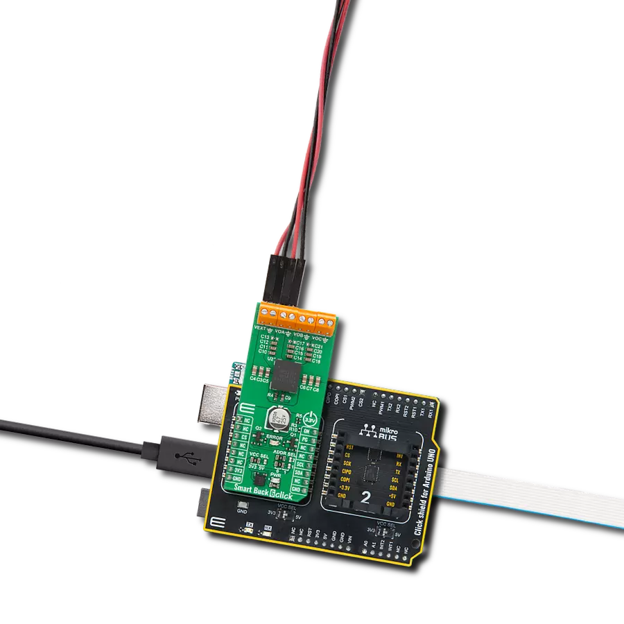
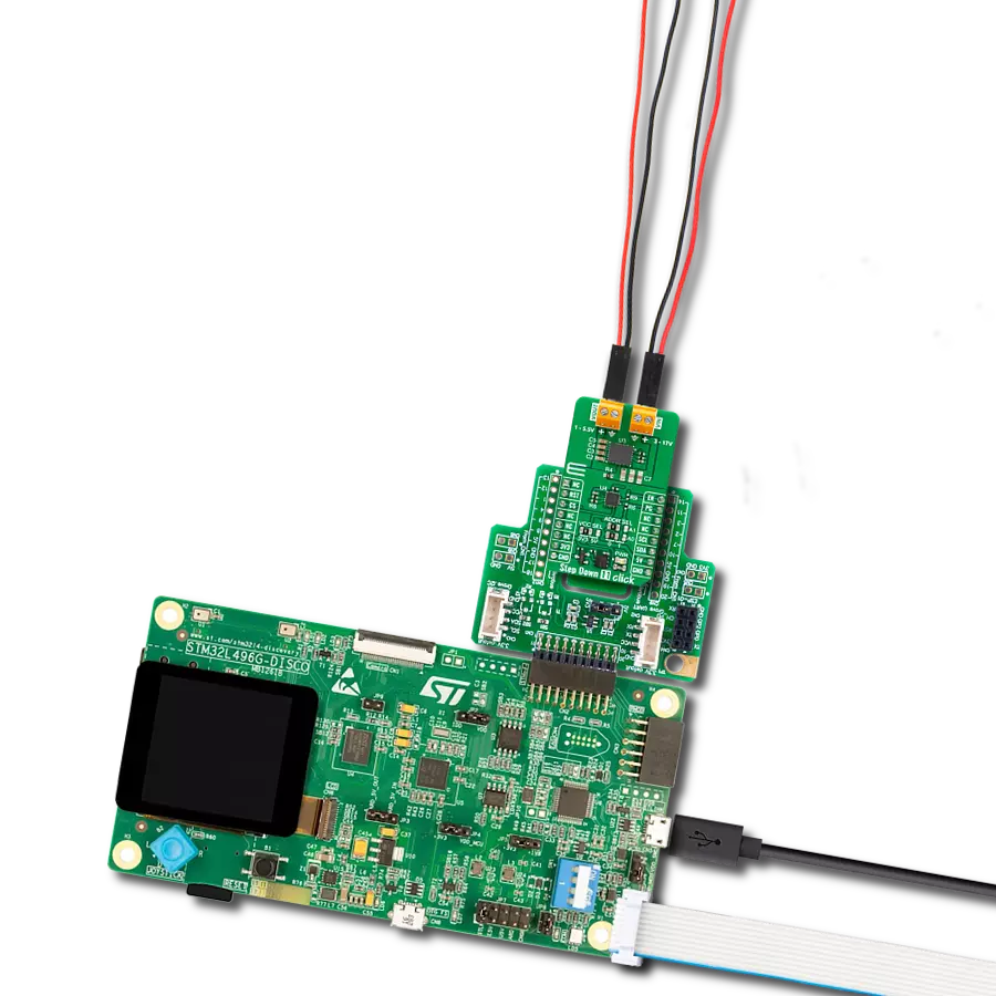
Start by selecting your development board and Click board™. Begin with the EasyPIC v8 as your development board.


Track your results in real time
Application Output
1. Application Output - In Debug mode, the 'Application Output' window enables real-time data monitoring, offering direct insight into execution results. Ensure proper data display by configuring the environment correctly using the provided tutorial.

2. UART Terminal - Use the UART Terminal to monitor data transmission via a USB to UART converter, allowing direct communication between the Click board™ and your development system. Configure the baud rate and other serial settings according to your project's requirements to ensure proper functionality. For step-by-step setup instructions, refer to the provided tutorial.

3. Plot Output - The Plot feature offers a powerful way to visualize real-time sensor data, enabling trend analysis, debugging, and comparison of multiple data points. To set it up correctly, follow the provided tutorial, which includes a step-by-step example of using the Plot feature to display Click board™ readings. To use the Plot feature in your code, use the function: plot(*insert_graph_name*, variable_name);. This is a general format, and it is up to the user to replace 'insert_graph_name' with the actual graph name and 'variable_name' with the parameter to be displayed.

Software Support
Library Description
This library contains API for Step Down 7 Click driver.
Key functions:
stepdown7_set_mode- Step Down 7 mode selection function.stepdown7_get_pg_state- Step Down 7 get PG pin state function.stepdown7_set_output- Step Down 7 set output voltage.
Open Source
Code example
The complete application code and a ready-to-use project are available through the NECTO Studio Package Manager for direct installation in the NECTO Studio. The application code can also be found on the MIKROE GitHub account.
/*!
 * @file main.c
 * @brief Step Down 7 Click example
 *
 * # Description
 * This library contains API for the Step Down 7 Click driver.
 * This driver provides the functions to set the output voltage treshold.
 *
 * The demo application is composed of two sections :
 *
 * ## Application Init
 * Initialization of I2C module and log UART.
 * After driver initialization, default settings sets output voltage to 1.5 V.
 *
 * ## Application Task
 * This example demonstrates the use of the Step Down 7 Click board™ by changing
 * output voltage every 5 seconds starting from 1.5 V up to 3.3 V.
 *
 * @author Stefan Ilic
 *
 */

#include "board.h"
#include "log.h"
#include "stepdown7.h"

static stepdown7_t stepdown7;
static log_t logger;

/**
 * @brief Output level printing function.
 * @details This function is used to log value of the selected voltage to UART terminal.
 * @param[in] sel_level : Selected voltage level.
 * @return Nothing.
 * @note None.
 */
static void print_selected_output_level ( uint8_t sel_level );

void application_init ( void )
{
    log_cfg_t log_cfg;  /**< Logger config object. */
    stepdown7_cfg_t stepdown7_cfg;  /**< Click config object. */

    /**
     * Logger initialization.
     * Default baud rate: 115200
     * Default log level: LOG_LEVEL_DEBUG
     * @note If USB_UART_RX and USB_UART_TX
     * are defined as HAL_PIN_NC, you will
     * need to define them manually for log to work.
     * See @b LOG_MAP_USB_UART macro definition for detailed explanation.
     */
    LOG_MAP_USB_UART( log_cfg );
    log_init( &logger, &log_cfg );
    log_info( &logger, " Application Init " );

    // Click initialization.
    stepdown7_cfg_setup( &stepdown7_cfg );
    STEPDOWN7_MAP_MIKROBUS( stepdown7_cfg, MIKROBUS_1 );
    if ( I2C_MASTER_ERROR == stepdown7_init( &stepdown7, &stepdown7_cfg ) )
    {
        log_error( &logger, " Communication init." );
        for ( ; ; );
    }

    if ( STEPDOWN7_ERROR == stepdown7_default_cfg ( &stepdown7 ) )
    {
        log_error( &logger, " Default configuration." );
        for ( ; ; );
    }
    log_info( &logger, " Application Task " );
}

void application_task ( void )
{
    for ( uint8_t n_cnt = STEPDOWN7_OUTPUT_1V5; n_cnt <= STEPDOWN7_OUTPUT_3V3; n_cnt++ )
    {
        stepdown7_set_output( &stepdown7, n_cnt );
        log_printf( &logger, " Selected output is:" );
        print_selected_output_level ( n_cnt );
        Delay_ms ( 1000 );
        Delay_ms ( 1000 );
        Delay_ms ( 1000 );
        Delay_ms ( 1000 );
        Delay_ms ( 1000 );
    }
}

int main ( void )
{
    /* Do not remove this line or clock might not be set correctly. */
    #ifdef PREINIT_SUPPORTED
    preinit();
    #endif

    application_init( );

    for ( ; ; )
    {
        application_task( );
    }

    return 0;
}

static void print_selected_output_level ( uint8_t sel_level )
{
    switch ( sel_level )
    {
        case ( STEPDOWN7_OUTPUT_1V5 ):
        {
            log_printf( &logger, " 1.5V\r\n" );
            break;
        }
        case ( STEPDOWN7_OUTPUT_2V5 ):
        {
            log_printf( &logger, " 2.5V\r\n" );
            break;
        }
        case ( STEPDOWN7_OUTPUT_3V3 ):
        {
            log_printf( &logger, " 3.3V\r\n" );
            break;
        }
        default:
        {
            log_printf( &logger, " ERROR\r\n" );
        }
    }
}

// ------------------------------------------------------------------------ END