Connect your devices for a seamless and efficient user experience using ST25R3916 and PIC18LF45K42
NFC revolution: Making your digital world a touch away

Published Oct 18, 2023
Click board™
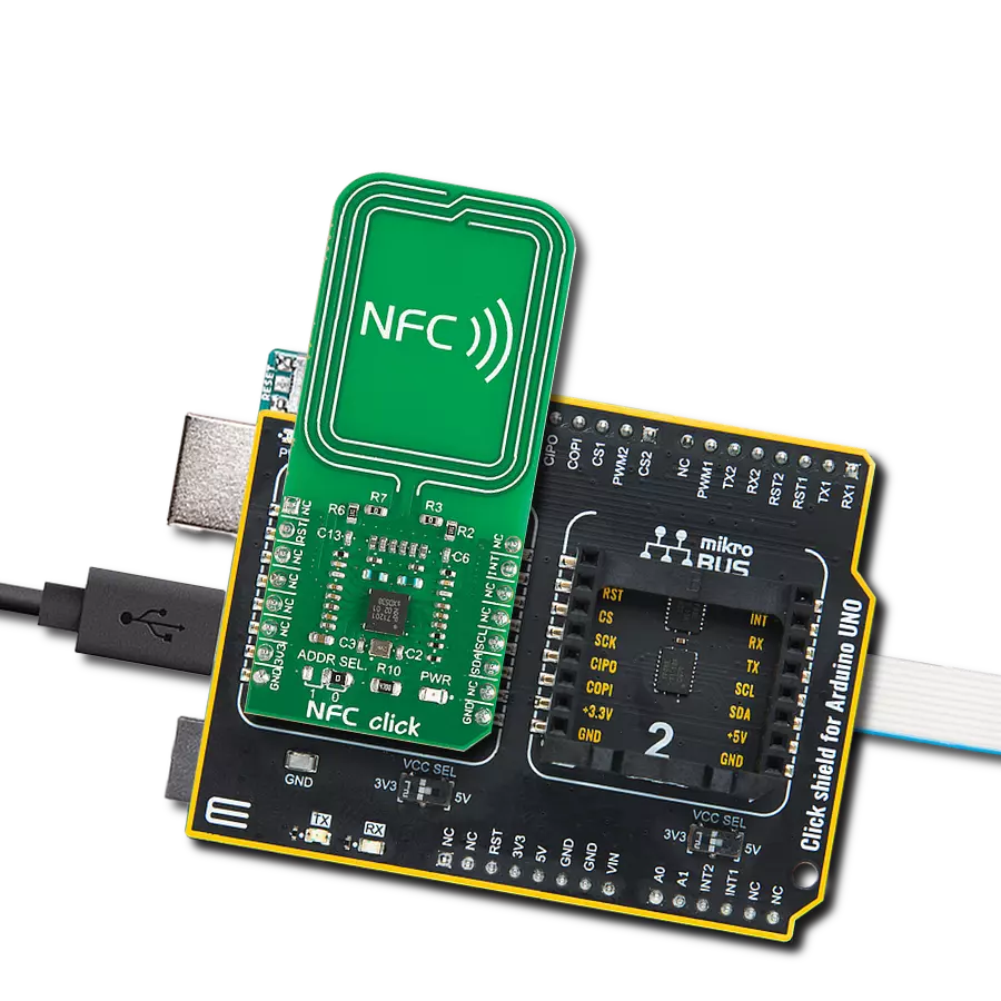
NFC 4 Click
Dev. board
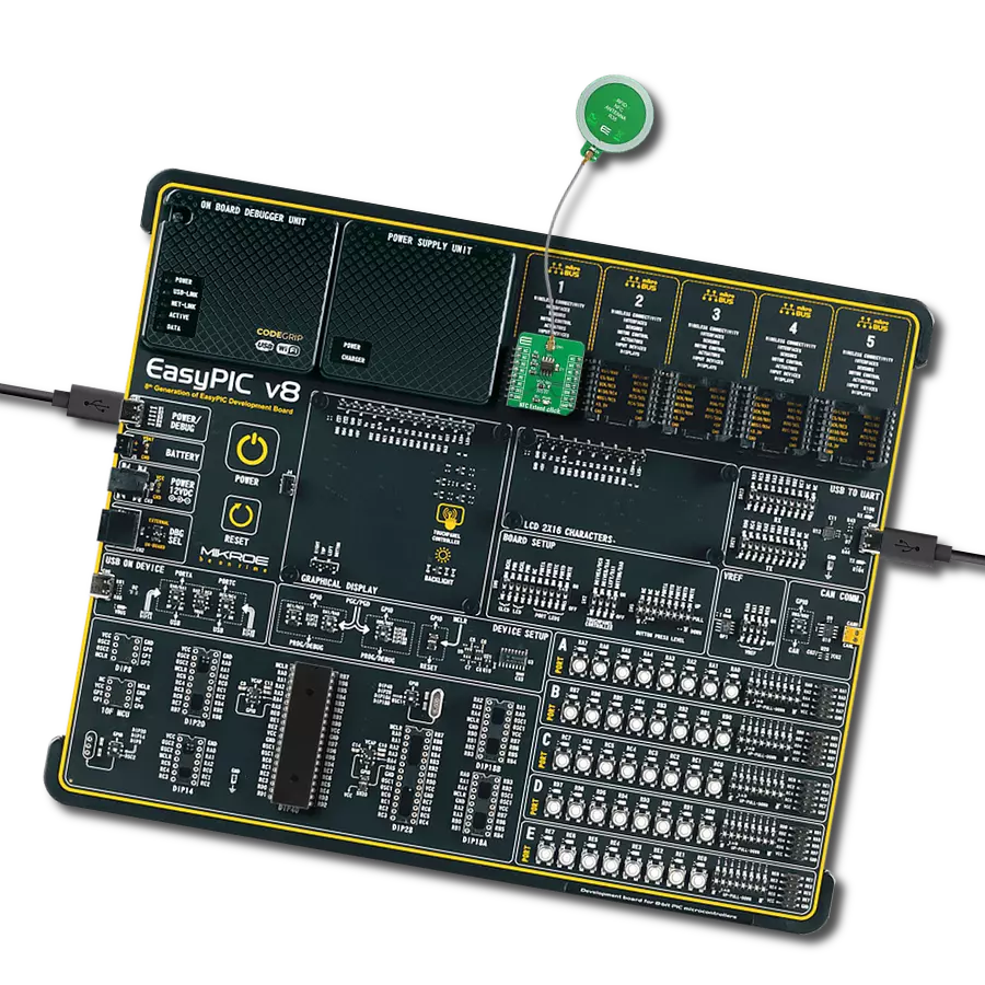
EasyPIC v8
Compiler
NECTO Studio
MCU
PIC18LF45K42
Join the NFC revolution and see how it's making your digital world accessible with a touch, enabling a new era of convenience and connectivity
A
A
Hardware Overview
How does it work?
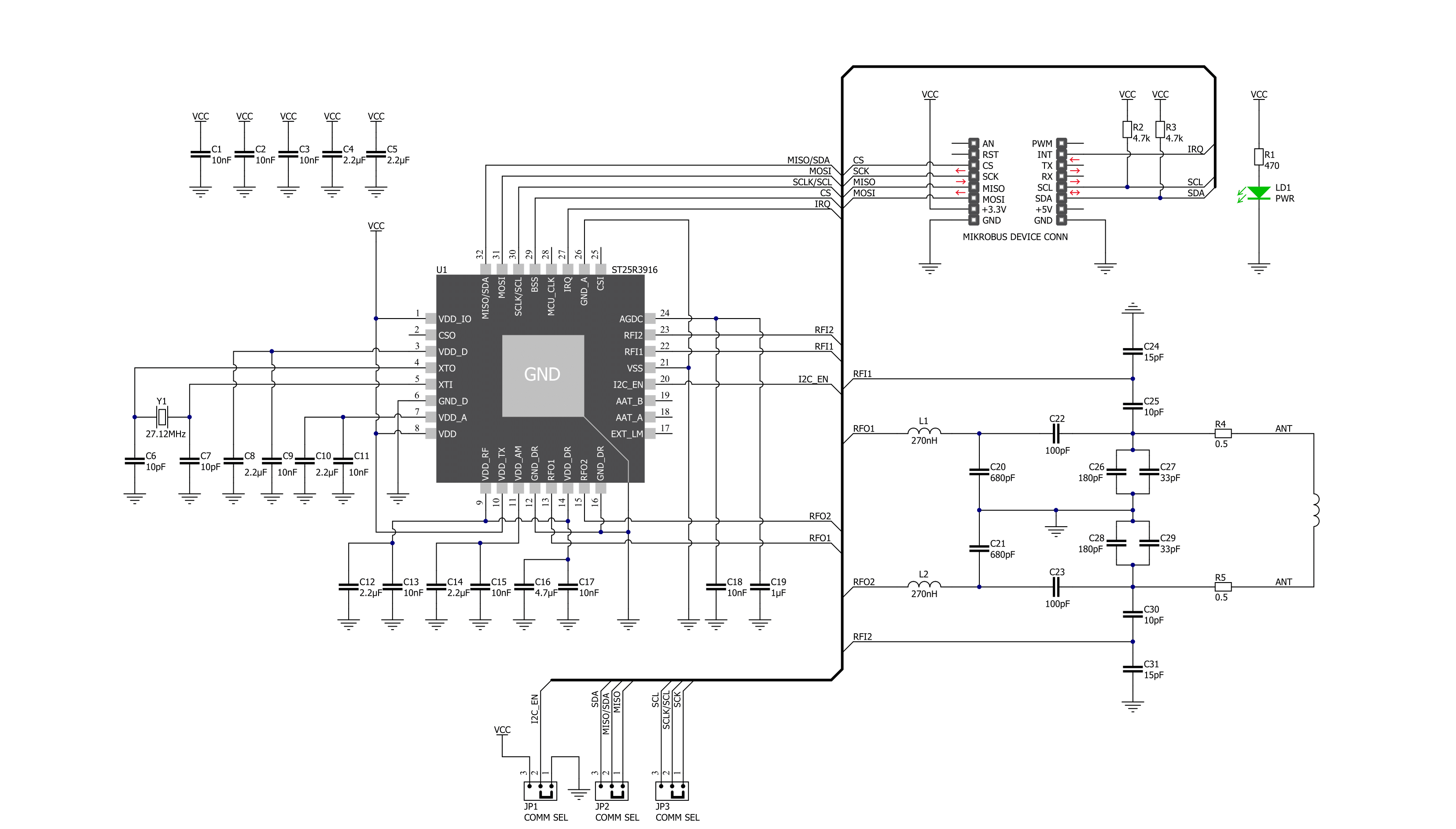
NFC 4 Click is based on the ST25R3916, a high-performance multi-purpose NFC transceiver supporting NFC initiator, NFC target, reader, and card emulation modes from STMicroelectronics. It features high RF output power to directly drive an antenna etched on the PCB, alongside its tuning circuit, at high efficiency. Besides being fully compliant with EMVCo 3.0, it also includes an advanced analog front end and a highly integrated data framing system for ISO 18092 passive and active initiator and target, NFC-A/B (ISO 14443A/B) reader including higher bit rates, NFC-F (FeliCa™) reader, NFC-V (ISO 15693) reader up to 53 kbps, and NFC-A / NFC-F card emulation. Due to this combination of high RF output power and low power modes, this Click board™ is ideally suited for infrastructure NFC applications. The ST25R3916 features a built-in A/D converter,
which input can be multiplexed from different sources for diagnostic functions and low-power card detection. The result of the A/D conversion is stored in a register that can be read through the selectable host interface. It also contains a low-power capacitive sensor to detect the presence of a card without switching on the reader field by measuring the amplitude or phase of the antenna signal. Also, an integrated low-power RC oscillator and a wake-up timer automatically wake up the ST25R3916 and check for the presence of a tag using one or more techniques of low-power detection of card presence (capacitive, phase, or amplitude). NFC 4 Click communicates with a microcontroller via an SPI interface or an I2C interface. The ST25R3916 acts as a peripheral device on both interfaces, relying on the microcontroller to initiate all communication. The
communication selection can be made by positioning SMD jumpers labeled COMM SEL to an appropriate position. Note that all the jumpers' positions must be on the same side, or the Click board™ may become unresponsive. This Click board™ also features an additional interrupt signal routed on the INT pin of the mikroBUS™ socket to notify the microcontroller of completed commands or external events (e.g., peer device field on). This Click board™ can be operated only with a 3.3V logic voltage level. The board must perform appropriate logic voltage level conversion before using MCUs with different logic levels. Also, it comes equipped with a library containing functions and an example code that can be used as a reference for further development.


Features overview
Development board
EasyPIC v8 is a development board specially designed for the needs of rapid development of embedded applications. It supports many high pin count 8-bit PIC microcontrollers from Microchip, regardless of their number of pins, and a broad set of unique functions, such as the first-ever embedded debugger/programmer. The development board is well organized and designed so that the end-user has all the necessary elements, such as switches, buttons, indicators, connectors, and others, in one place. Thanks to innovative manufacturing technology, EasyPIC v8 provides a fluid and immersive working experience, allowing access anywhere and under any
circumstances at any time. Each part of the EasyPIC v8 development board contains the components necessary for the most efficient operation of the same board. In addition to the advanced integrated CODEGRIP programmer/debugger module, which offers many valuable programming/debugging options and seamless integration with the Mikroe software environment, the board also includes a clean and regulated power supply module for the development board. It can use a wide range of external power sources, including a battery, an external 12V power supply, and a power source via the USB Type-C (USB-C) connector.
Communication options such as USB-UART, USB DEVICE, and CAN are also included, including the well-established mikroBUS™ standard, two display options (graphical and character-based LCD), and several different DIP sockets. These sockets cover a wide range of 8-bit PIC MCUs, from the smallest PIC MCU devices with only eight up to forty pins. EasyPIC v8 is an integral part of the Mikroe ecosystem for rapid development. Natively supported by Mikroe software tools, it covers many aspects of prototyping and development thanks to a considerable number of different Click boards™ (over a thousand boards), the number of which is growing every day.

Microcontroller Overview
MCU Card / MCU
Architecture
PIC
MCU Memory (KB)
32
Silicon Vendor
Microchip
Pin count
40
RAM (Bytes)
2048
Used MCU Pins
mikroBUS™ mapper
Take a closer look
Click board™ Schematic
Step by step
Project assembly

Start by selecting your development board and Click board™. Begin with the EasyPIC v8 as your development board.


Software Support
Library Description
This library contains API for NFC 4 Click driver.
Key functions:
nfc4_get_mifare_tag_uid- This function reads the UID of a mifare tag.nfc4_write_register- This function writes a desired data to the selected register.nfc4_read_register- This function reads a desired data from the selected register.
Open Source
Code example
The complete application code and a ready-to-use project are available through the NECTO Studio Package Manager for direct installation in the NECTO Studio. The application code can also be found on the MIKROE GitHub account.
/*!
 * @file main.c
 * @brief NFC4 Click example
 *
 * # Description
 * This example demonstrates the use of NFC 4 Click board
 * by reading MIFARE ISO/IEC 14443 type A tag UID.
 *
 * The demo application is composed of two sections :
 *
 * ## Application Init
 * Initializes the driver and performs the Click default configuration.
 *
 * ## Application Task
 * If there's a tag detected, it reads its UID and displays it on the USB UART every 500ms.
 *
 * @note
 * For testing purposes we used MIKROE-1475 - an RFiD tag 13.56MHz compliant with ISO14443-A standard.
 *
 * @author Stefan Filipovic
 *
 */

#include "board.h"
#include "log.h"
#include "nfc4.h"

static nfc4_t nfc4;
static log_t logger;

void application_init ( void )
{
    log_cfg_t log_cfg;      /**< Logger config object. */
    nfc4_cfg_t nfc4_cfg;    /**< Click config object. */

    /**
     * Logger initialization.
     * Default baud rate: 115200
     * Default log level: LOG_LEVEL_DEBUG
     * @note If USB_UART_RX and USB_UART_TX
     * are defined as HAL_PIN_NC, you will
     * need to define them manually for log to work.
     * See @b LOG_MAP_USB_UART macro definition for detailed explanation.
     */
    LOG_MAP_USB_UART( log_cfg );
    log_init( &logger, &log_cfg );
    log_info( &logger, " Application Init " );

    // Click initialization.
    nfc4_cfg_setup( &nfc4_cfg );
    NFC4_MAP_MIKROBUS( nfc4_cfg, MIKROBUS_1 );
    err_t init_flag  = nfc4_init( &nfc4, &nfc4_cfg );
    if ( ( I2C_MASTER_ERROR == init_flag ) || ( SPI_MASTER_ERROR == init_flag ) )
    {
        log_error( &logger, " Application Init Error. " );
        log_info( &logger, " Please, run program again... " );

        for ( ; ; );
    }

    NFC4_SET_DATA_SAMPLE_EDGE;

    if ( NFC4_ERROR == nfc4_default_cfg ( &nfc4 ) )
    {
        log_error( &logger, " Default Config Error. " );
        log_info( &logger, " Please, run program again... " );

        for ( ; ; );
    }

    log_info( &logger, " Application Task " );
}

void application_task ( void )
{
    uint8_t tag_uid[ 10 ] = { 0 };
    uint8_t uid_len = 0;

    if( NFC4_OK == nfc4_get_mifare_tag_uid( &nfc4, tag_uid, &uid_len ) )
    {
        log_printf( &logger, " Tag UID: " );
        for ( uint8_t cnt = 0; cnt < uid_len; cnt++ )
        {
            log_printf( &logger, "%.2X", ( uint16_t ) tag_uid[ cnt ] );
        }
        log_printf( &logger, "\r\n" );
        Delay_ms ( 500 );
    }
}

int main ( void )
{
    /* Do not remove this line or clock might not be set correctly. */
    #ifdef PREINIT_SUPPORTED
    preinit();
    #endif

    application_init( );

    for ( ; ; )
    {
        application_task( );
    }

    return 0;
}

// ------------------------------------------------------------------------ END