Experience the future of touch interaction with IQS227D and PIC18F26K40
Advanced touch recognition

Published Nov 01, 2023
Click board™
Cap Touch 6 Click
Dev. board
EasyPIC v8
Compiler
NECTO Studio
MCU
PIC18F26K40
Ready to engineer the next generation of touch-sensitive applications? Explore the possibilities of our advanced capacitive touch sensing
A
A
Hardware Overview
How does it work?
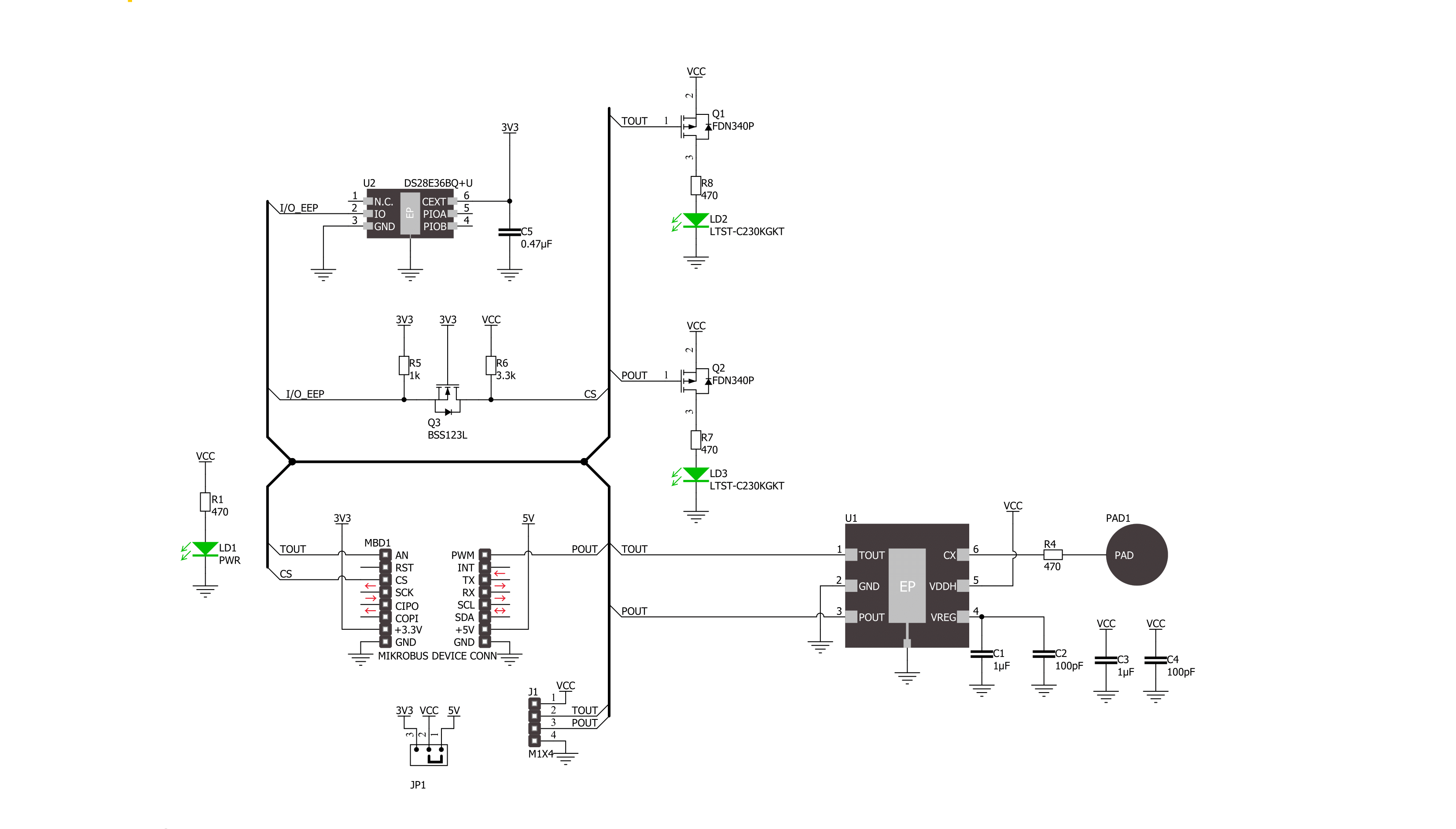
Cap Touch 6 Click is based on the IQS227D, a fully integrated single-channel capacitive controller with an internal voltage regular and reference capacitor from Azoteq. As known, the capacitive touch technology works by detecting changes in capacitance on the screen or touchpad, in this case, the sensing area at the top of the frontal side of the board, when a finger or other conductive object comes into contact with it. The IQS227D is built on ProxSense® low voltage platform, ideal for battery application, and comes with dual outputs (touch and proximity outputs don't need to be configured), a low-power mode while sensing
proximity, and an advanced on-chip digital signal processing. Touch and proximity features, alongside its mikroBUS™ pins, marked TOU and POU, only used to communicate with MCU, also have their corresponding LED indicators, labeled Touch and Proximity, reporting the activity of these features. If a touch/proximity event is detected on the onboard sensing pad, the state of the corresponding LED will be changed, indicating an activated channel. In addition to pins of the mikroBUS™ socket, these functions can also be found on the unpopulated header for external uses if they are necessary for the user in some
specific application. As mentioned earlier, this board contains a capacitive sensing area that is the only element on the top side of the board, allowing the protective acrylic plexiglass layer placement. This Click board™ can operate with either 3.3V or 5V logic voltage levels selected via the VCC SEL jumper. This way, both 3.3V and 5V capable MCUs can use the communication lines properly. Also, this Click board™ comes equipped with a library containing easy-to-use functions and an example code that can be used, as a reference, for further development.


Features overview
Development board
EasyPIC v8 is a development board specially designed for the needs of rapid development of embedded applications. It supports many high pin count 8-bit PIC microcontrollers from Microchip, regardless of their number of pins, and a broad set of unique functions, such as the first-ever embedded debugger/programmer. The development board is well organized and designed so that the end-user has all the necessary elements, such as switches, buttons, indicators, connectors, and others, in one place. Thanks to innovative manufacturing technology, EasyPIC v8 provides a fluid and immersive working experience, allowing access anywhere and under any
circumstances at any time. Each part of the EasyPIC v8 development board contains the components necessary for the most efficient operation of the same board. In addition to the advanced integrated CODEGRIP programmer/debugger module, which offers many valuable programming/debugging options and seamless integration with the Mikroe software environment, the board also includes a clean and regulated power supply module for the development board. It can use a wide range of external power sources, including a battery, an external 12V power supply, and a power source via the USB Type-C (USB-C) connector.
Communication options such as USB-UART, USB DEVICE, and CAN are also included, including the well-established mikroBUS™ standard, two display options (graphical and character-based LCD), and several different DIP sockets. These sockets cover a wide range of 8-bit PIC MCUs, from the smallest PIC MCU devices with only eight up to forty pins. EasyPIC v8 is an integral part of the Mikroe ecosystem for rapid development. Natively supported by Mikroe software tools, it covers many aspects of prototyping and development thanks to a considerable number of different Click boards™ (over a thousand boards), the number of which is growing every day.

Microcontroller Overview
MCU Card / MCU
Architecture
PIC
MCU Memory (KB)
64
Silicon Vendor
Microchip
Pin count
28
RAM (Bytes)
3728
Used MCU Pins
mikroBUS™ mapper
Take a closer look
Click board™ Schematic
Step by step
Project assembly

Start by selecting your development board and Click board™. Begin with the EasyPIC v8 as your development board.


Software Support
Library Description
This library contains API for Cap Touch 6 Click driver.
Key functions:
captouch6_get_tout_pin- This function returns the TOUT pin logic statecaptouch6_get_pout_pin- This function returns the POUT pin logic state
Open Source
Code example
The complete application code and a ready-to-use project are available through the NECTO Studio Package Manager for direct installation in the NECTO Studio. The application code can also be found on the MIKROE GitHub account.
/*!
 * @file main.c
 * @brief Cap Touch 6 Click Example.
 *
 * # Description
 * This example demonstrates the use of Cap Touch 6 Click board by reading and displaying
 * the touch and proximity events.
 *
 * The demo application is composed of two sections :
 *
 * ## Application Init
 * Initializes the driver and logger.
 *
 * ## Application Task
 * Reads the touch and proximity event pins state and displays them on the USB UART on changes.
 *
 * @author Stefan Filipovic
 *
 */

#include "board.h"
#include "log.h"
#include "captouch6.h"

static captouch6_t captouch6;   /**< Cap Touch 6 Click driver object. */
static log_t logger;    /**< Logger object. */

void application_init ( void )
{
    log_cfg_t log_cfg;  /**< Logger config object. */
    captouch6_cfg_t captouch6_cfg;  /**< Click config object. */

    /**
     * Logger initialization.
     * Default baud rate: 115200
     * Default log level: LOG_LEVEL_DEBUG
     * @note If USB_UART_RX and USB_UART_TX
     * are defined as HAL_PIN_NC, you will
     * need to define them manually for log to work.
     * See @b LOG_MAP_USB_UART macro definition for detailed explanation.
     */
    LOG_MAP_USB_UART( log_cfg );
    log_init( &logger, &log_cfg );
    log_info( &logger, " Application Init " );

    // Click initialization.
    captouch6_cfg_setup( &captouch6_cfg );
    CAPTOUCH6_MAP_MIKROBUS( captouch6_cfg, MIKROBUS_1 );
    if ( DIGITAL_OUT_UNSUPPORTED_PIN == captouch6_init( &captouch6, &captouch6_cfg ) )
    {
        log_error( &logger, " Communication init." );
        for ( ; ; );
    }
    log_info( &logger, " Application Task " );
}

void application_task ( void )
{
    static uint8_t old_touch_state = 0, old_prox_state = 0;
    uint8_t touch_state = captouch6_get_tout_pin ( &captouch6 );
    uint8_t prox_state = captouch6_get_pout_pin ( &captouch6 );
    if ( ( old_touch_state != touch_state ) || ( old_prox_state != prox_state ) )
    {
        log_printf( &logger, " Touch: %s\r\n", ( char * ) ( !touch_state ? "detected" : "idle" ) );
        log_printf( &logger, " Proximity: %s\r\n\n", ( char * ) ( !prox_state ? "detected" : "idle" ) );
        old_touch_state = touch_state;
        old_prox_state = prox_state;
    }
}

int main ( void )
{
    /* Do not remove this line or clock might not be set correctly. */
    #ifdef PREINIT_SUPPORTED
    preinit();
    #endif

    application_init( );

    for ( ; ; )
    {
        application_task( );
    }

    return 0;
}

// ------------------------------------------------------------------------ END


