Unleash the power of persistent memory with S-34C04AB and PIC18F2455
Store, retrieve, and rewrite data with unparalleled speed and efficiency
Published Nov 01, 2023
Click board™
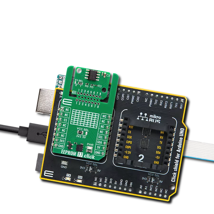
EEPROM 11 Click
Dev. board
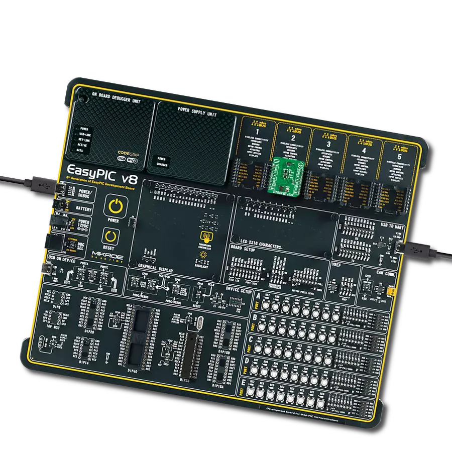
EasyPIC v8
Compiler
NECTO Studio
MCU
PIC18F2455
Explore the limitless possibilities of data storage with our EEPROM solution.
A
A
Hardware Overview
How does it work?
EEPROM 11 Click is based on the S-34C04AB, an EEPROM memory for DIMM serial presence detection from ABLIC. The EEPROM uses a Schmitt trigger and noise filter on the I2C bus for noise suppression. The S-34C04AB has a timeout function that can reset the I2C interface and return to standby mode. This timeout is typically 30ms. The EEPROM also allows you to write a byte or a page. The page write mode allows up to 16
bytes to be written in a single operation. The IC also has set protection for block n, clear write protection for all blocks, and read protection status for block n. As for reading, you can read a current address, a random read, or a sequential read. EEPROM 11 Click uses a standard 2-wire I2C interface to communicate with the host MCU, supporting clock frequencies of up to 1MHz. You can set the desired I2C address over three ADDR
SEL jumpers, with 0s selected by default. This Click board™ can be operated only with a 3.3V logic voltage level. The board must perform appropriate logic voltage level conversion before using MCUs with different logic levels. Also, this Click board™ comes equipped with a library containing easy-to-use functions and an example code that can be used as a reference for further development.

Features overview
Development board
EasyPIC v8 is a development board specially designed for the needs of rapid development of embedded applications. It supports many high pin count 8-bit PIC microcontrollers from Microchip, regardless of their number of pins, and a broad set of unique functions, such as the first-ever embedded debugger/programmer. The development board is well organized and designed so that the end-user has all the necessary elements, such as switches, buttons, indicators, connectors, and others, in one place. Thanks to innovative manufacturing technology, EasyPIC v8 provides a fluid and immersive working experience, allowing access anywhere and under any
circumstances at any time. Each part of the EasyPIC v8 development board contains the components necessary for the most efficient operation of the same board. In addition to the advanced integrated CODEGRIP programmer/debugger module, which offers many valuable programming/debugging options and seamless integration with the Mikroe software environment, the board also includes a clean and regulated power supply module for the development board. It can use a wide range of external power sources, including a battery, an external 12V power supply, and a power source via the USB Type-C (USB-C) connector.
Communication options such as USB-UART, USB DEVICE, and CAN are also included, including the well-established mikroBUS™ standard, two display options (graphical and character-based LCD), and several different DIP sockets. These sockets cover a wide range of 8-bit PIC MCUs, from the smallest PIC MCU devices with only eight up to forty pins. EasyPIC v8 is an integral part of the Mikroe ecosystem for rapid development. Natively supported by Mikroe software tools, it covers many aspects of prototyping and development thanks to a considerable number of different Click boards™ (over a thousand boards), the number of which is growing every day.

Microcontroller Overview
MCU Card / MCU

Architecture
PIC
MCU Memory (KB)
24
Silicon Vendor
Microchip
Pin count
28
RAM (Bytes)
2048
Used MCU Pins
mikroBUS™ mapper
Take a closer look
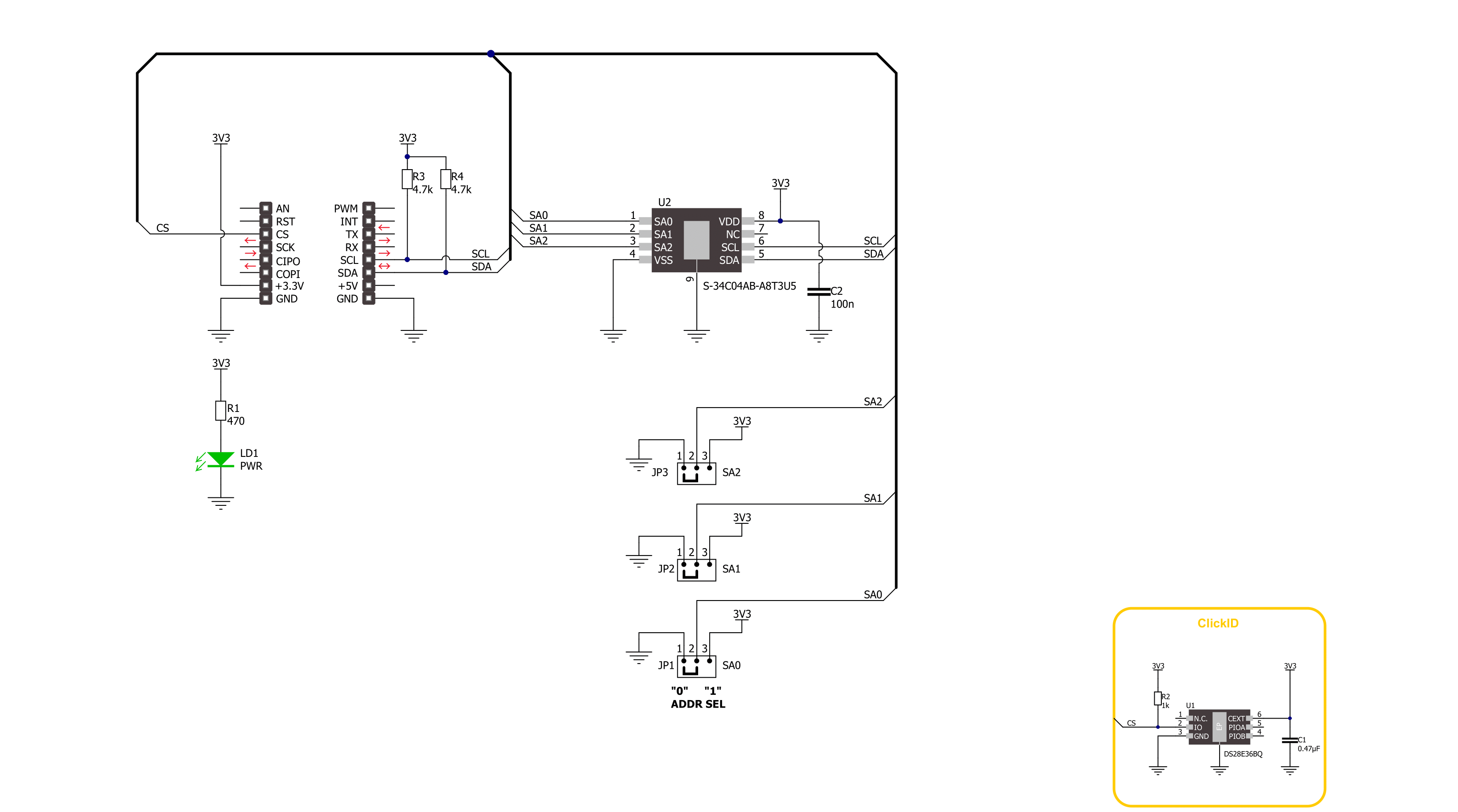
Click board™ Schematic
Step by step
Project assembly

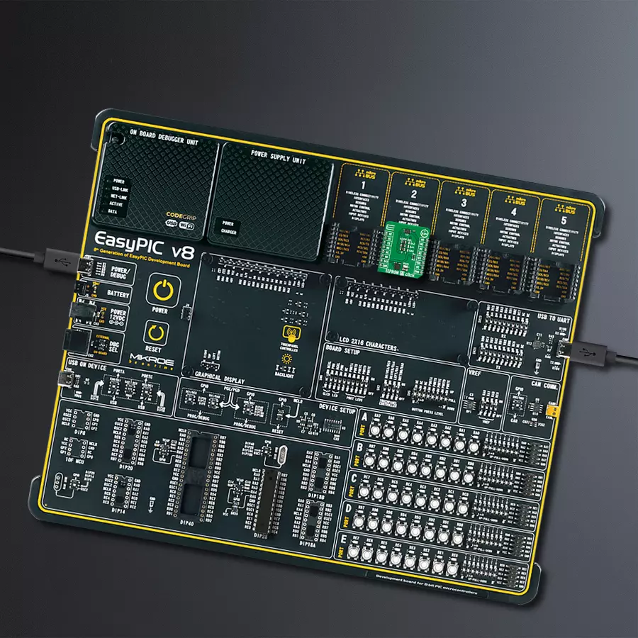
Start by selecting your development board and Click board™. Begin with the EasyPIC v8 as your development board.


Software Support
Library Description
This library contains API for EEPROM 11 Click driver.
Key functions:
eeprom11_page_write- EEPROM 11 page write function.eeprom11_clear_page- EEPROM 11 page clear function.eeprom11_set_page_addr- EEPROM 11 set page address function.
Open Source
Code example
The complete application code and a ready-to-use project are available through the NECTO Studio Package Manager for direct installation in the NECTO Studio. The application code can also be found on the MIKROE GitHub account.
/*!
 * @file main.c
 * @brief EEPROM 11 Click example
 *
 * # Description
 * This is an example that demonstrates the use of the EEPROM 11 Click board.
 *
 * The demo application is composed of two sections :
 *
 * ## Application Init
 * Initializes the driver and USB UART logging, disables write protection.
 *
 * ## Application Task
 * Writes a desired number of data bytes to the EEPROM 11 memory into a specified address,
 * and verifies that it is written correctly by reading from the same memory location.
 *
 * @author Stefan Ilic
 *
 */

#include "board.h"
#include "log.h"
#include "eeprom11.h"

#define TX_DATA         "EEPROM 11 Click"
#define MEMORY_ADDRESS  0x00

static eeprom11_t eeprom11;
static log_t logger;

void application_init ( void )
{
    log_cfg_t log_cfg;  /**< Logger config object. */
    eeprom11_cfg_t eeprom11_cfg;  /**< Click config object. */

    /**
     * Logger initialization.
     * Default baud rate: 115200
     * Default log level: LOG_LEVEL_DEBUG
     * @note If USB_UART_RX and USB_UART_TX
     * are defined as HAL_PIN_NC, you will
     * need to define them manually for log to work.
     * See @b LOG_MAP_USB_UART macro definition for detailed explanation.
     */
    LOG_MAP_USB_UART( log_cfg );
    log_init( &logger, &log_cfg );
    log_info( &logger, " Application Init " );

    // Click initialization.
    eeprom11_cfg_setup( &eeprom11_cfg );
    EEPROM11_MAP_MIKROBUS( eeprom11_cfg, MIKROBUS_1 );
    if ( I2C_MASTER_ERROR == eeprom11_init( &eeprom11, &eeprom11_cfg ) )
    {
        log_error( &logger, " Communication init." );
        for ( ; ; );
    }

    if ( EEPROM11_ERROR == eeprom11_default_cfg ( &eeprom11 ) )
    {
        log_error( &logger, " Default configuration." );
        for ( ; ; );
    }

    log_info( &logger, " Application Task " );
}

void application_task ( void )
{
    err_t error_flag = EEPROM11_OK;
    uint8_t rx_data[ 16 ] = { 0 };
    uint8_t tx_data[ 16 ] = TX_DATA;

    eeprom11_clear_page( &eeprom11, MEMORY_ADDRESS );
    Delay_ms ( 1000 );
    error_flag = eeprom11_page_write( &eeprom11, MEMORY_ADDRESS, tx_data );
    if ( EEPROM11_OK == error_flag )
    {
        log_printf( &logger, " Write data: %s \r\n", tx_data );
    }
    else
    {
        log_error( &logger, " Write operation failed!!! " );
    }
    Delay_ms ( 1000 );

    error_flag = eeprom11_generic_read( &eeprom11, MEMORY_ADDRESS, rx_data, 15 );
    if ( EEPROM11_OK == error_flag )
    {
        log_printf( &logger, "Read data: %s \r\n", rx_data );
    }
    else
    {
        log_error( &logger, " Write operation failed!!! " );
    }
    log_printf( &logger, " - - - - - - - - - - - \r\n" );

    Delay_ms ( 1000 );
    Delay_ms ( 1000 );
}

int main ( void )
{
    /* Do not remove this line or clock might not be set correctly. */
    #ifdef PREINIT_SUPPORTED
    preinit();
    #endif

    application_init( );

    for ( ; ; )
    {
        application_task( );
    }

    return 0;
}

// ------------------------------------------------------------------------ END