Achieve precise environmental HVAC sensing with SCD41, SPS30 and PIC18F2458
Redefining comfort with compact HVAC innovation
Published Nov 01, 2023
Click board™
HVAC Click
Dev. board
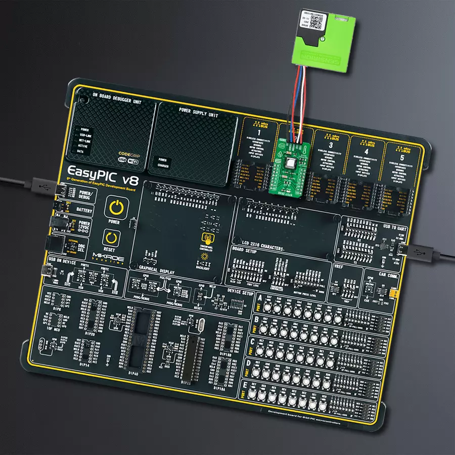
EasyPIC v8
Compiler
NECTO Studio
MCU
PIC18F2458
Harness real-time data from the miniature CO2 and PM sensors to dynamically adjust ventilation rates, ensuring optimal indoor air quality in response to varying occupancy and pollutant levels
A
A
Hardware Overview
How does it work?
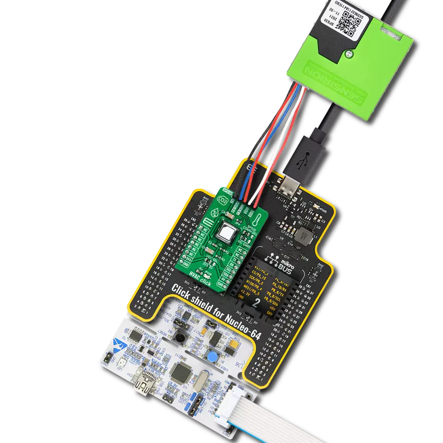
HVAC Click is based on the SCD41, a Sensirion's next-generation miniature CO2 sensor. This carbon dioxide sensor builds on the photoacoustic sensing principle and Sensirion's patented PASens® and CMOSens® technology to offer high accuracy at a minor form factor. It operates within a specified range from 400 to 5'000 ppm, configurable through the I2C interface with a low-power single-shot mode supported to reduce noise levels, i.e., on-demand measurement. The SCD41 features on-chip signal compensation to counteract pressure and temperature effects. Feeding the SCD41 with the pressure or altitude enables the highest accuracy of the CO2 output signal across an extensive pressure range. Setting the temperature offset improves the accuracy of the relative humidity and temperature
output signal. Note that the temperature offset does not impact the accuracy of the CO2 output. HVAC Click communicates with MCU using the standard I2C 2-Wire interface to read data and configure settings, supporting Standard mode operation with a clock frequency up to 100kHz. Furthermore, this Click board™ is suitable for indoor air quality applications using an additional SPS30, a Particulate Matter (PM) sensor from Sensirion, with the help of which the HVAC Click in the most energy-efficient and human-friendly way maintains a low CO2 concentration for a healthy, productive environment. The measurement principle of the SPS30 is based on laser scattering, which, together with high quality, enables precise measurements from its first operation and throughout its lifetime of more than ten years.
In addition, the SPS30 allows using both I2C and UART interfaces, where the communication interface selection can be made by positioning SMD jumpers labeled COMM SEL to an appropriate position. Note that all the jumpers' positions must be on the same side, or the Click board™ may become unresponsive. Also, to activate I2C communication, the JP4 jumper must be populated. This Click board™ can operate with either 3.3V or 5V logic voltage levels selected via the VCC SEL jumper. This way, both 3.3V and 5V capable MCUs can use the communication lines properly. Also, this Click board™ comes equipped with a library containing easy-to-use functions and an example code that can be used, as a reference, for further development.

Features overview
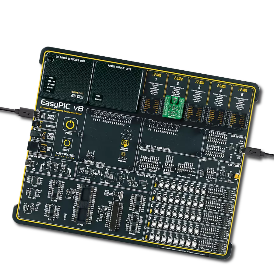
Development board
EasyPIC v8 is a development board specially designed for the needs of rapid development of embedded applications. It supports many high pin count 8-bit PIC microcontrollers from Microchip, regardless of their number of pins, and a broad set of unique functions, such as the first-ever embedded debugger/programmer. The development board is well organized and designed so that the end-user has all the necessary elements, such as switches, buttons, indicators, connectors, and others, in one place. Thanks to innovative manufacturing technology, EasyPIC v8 provides a fluid and immersive working experience, allowing access anywhere and under any
circumstances at any time. Each part of the EasyPIC v8 development board contains the components necessary for the most efficient operation of the same board. In addition to the advanced integrated CODEGRIP programmer/debugger module, which offers many valuable programming/debugging options and seamless integration with the Mikroe software environment, the board also includes a clean and regulated power supply module for the development board. It can use a wide range of external power sources, including a battery, an external 12V power supply, and a power source via the USB Type-C (USB-C) connector.
Communication options such as USB-UART, USB DEVICE, and CAN are also included, including the well-established mikroBUS™ standard, two display options (graphical and character-based LCD), and several different DIP sockets. These sockets cover a wide range of 8-bit PIC MCUs, from the smallest PIC MCU devices with only eight up to forty pins. EasyPIC v8 is an integral part of the Mikroe ecosystem for rapid development. Natively supported by Mikroe software tools, it covers many aspects of prototyping and development thanks to a considerable number of different Click boards™ (over a thousand boards), the number of which is growing every day.

Microcontroller Overview
MCU Card / MCU
Architecture
PIC
MCU Memory (KB)
24
Silicon Vendor
Microchip
Pin count
28
RAM (Bytes)
2048
You complete me!
Accessories
SPS30 PM2.5 Particulate Matter sensor is based on laser scattering and uses Sensirion’s innovative contamination-resistance technology. Due to their small size, PM2.5 particles can travel deep into the human lung and cause various health issues, for instance, by triggering asthma attacks or contributing to cardiovascular disease. The SPS30 enables precise measurements from its first operation and throughout its lifetime of more than ten years. A sensing solution that works over the whole lifetime, assuring good air quality to the final user and increasing energy efficiency and sustainable operation.

Used MCU Pins
mikroBUS™ mapper
Take a closer look
Click board™ Schematic

Step by step
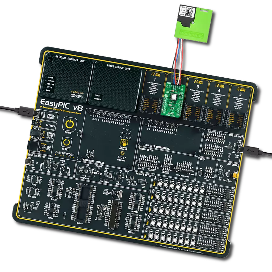
Project assembly

Start by selecting your development board and Click board™. Begin with the EasyPIC v8 as your development board.


Track your results in real time
Application Output
1. Application Output - In Debug mode, the 'Application Output' window enables real-time data monitoring, offering direct insight into execution results. Ensure proper data display by configuring the environment correctly using the provided tutorial.

2. UART Terminal - Use the UART Terminal to monitor data transmission via a USB to UART converter, allowing direct communication between the Click board™ and your development system. Configure the baud rate and other serial settings according to your project's requirements to ensure proper functionality. For step-by-step setup instructions, refer to the provided tutorial.

3. Plot Output - The Plot feature offers a powerful way to visualize real-time sensor data, enabling trend analysis, debugging, and comparison of multiple data points. To set it up correctly, follow the provided tutorial, which includes a step-by-step example of using the Plot feature to display Click board™ readings. To use the Plot feature in your code, use the function: plot(*insert_graph_name*, variable_name);. This is a general format, and it is up to the user to replace 'insert_graph_name' with the actual graph name and 'variable_name' with the parameter to be displayed.

Software Support
Library Description
This library contains API for HVAC Click driver.
Key functions:
hvac_sps30_start_measurement- SPS30 start measurement command functionhvac_sps30_get_ready_flag- SPS30 get ready flag functionhvac_sps30_read_measured_data- SPS30 read measured data function.
Open Source
Code example
The complete application code and a ready-to-use project are available through the NECTO Studio Package Manager for direct installation in the NECTO Studio. The application code can also be found on the MIKROE GitHub account.
/*!
 * @file main.c
 * @brief Hvac Click example
 *
 * # Description
 * This is an example that demonstrates the use of the HVAC Click board.
 *
 * The demo application is composed of two sections :
 *
 * ## Application Init
 * Initialization driver enables - I2C,
 * SCD40: perform factory reset, serial number, features, product type platform type,
 * product version and
 * SPS30: perform start measurement mode, also write log.
 *
 * ## Application Task
 * This is an example which demonstrates the use of HVAC Click board.
 * HVAC Click board can be used to measure :
 * Concentration of CO2 in air,
 * Temperature ( degree Celsius ),
 * Relative Humidity ( % ),
 * Mass Concentration of PM1.0, PM2.5, PM4.0, PM10 and
 * Number Concentration of PM0.5, PM1.0, PM2.5, PM4.0 and PM10.
 * All data logs write on USB uart changes.
 *
 * @author Stefan Ilic
 *
 */

#include "board.h"
#include "log.h"
#include "hvac.h"

static hvac_t hvac;
static log_t logger;
measuremen_data_t hvac_data;
feature_data_t version_data;
mass_and_num_cnt_data_t sps30_data;
uint16_t ser_num[ 3 ];

void application_init ( void )
{
    log_cfg_t log_cfg;  /**< Logger config object. */
    hvac_cfg_t hvac_cfg;  /**< Click config object. */

    /**
     * Logger initialization.
     * Default baud rate: 115200
     * Default log level: LOG_LEVEL_DEBUG
     * @note If USB_UART_RX and USB_UART_TX
     * are defined as HAL_PIN_NC, you will
     * need to define them manually for log to work.
     * See @b LOG_MAP_USB_UART macro definition for detailed explanation.
     */
    LOG_MAP_USB_UART( log_cfg );
    log_init( &logger, &log_cfg );
    log_info( &logger, " Application Init " );

    // Click initialization.
    hvac_cfg_setup( &hvac_cfg );
    HVAC_MAP_MIKROBUS( hvac_cfg, MIKROBUS_1 );
    if ( I2C_MASTER_ERROR == hvac_init( &hvac, &hvac_cfg ) )
    {
        log_error( &logger, " Communication init." );
        for ( ; ; );
    }

    log_info( &logger, " Application Task " );
    Delay_ms ( 1000 );
    hvac_scd40_send_cmd( &hvac, HVAC_PERFORM_FACTORY_RESET );
    log_printf( &logger, "  Perform Factory Reset   \r\n" );
    log_printf( &logger, "--------------------------\r\n" );
    Delay_ms ( 1000 );
    Delay_ms ( 1000 );

    hvac_scd40_get_serial_number ( &hvac, ser_num );
    log_printf( &logger, "   SCD40 - Serial Number : %.4d-%.4d-%.4d \r\n",
                ( uint16_t ) ser_num[ 0 ], ( uint16_t ) ser_num[ 1 ], ( uint16_t ) ser_num[ 2 ] );
    log_printf( &logger, "--------------------------\r\n" );
    Delay_ms ( 100 );
    hvac_scd40_get_feature_set_version( &hvac, &version_data );
    log_printf( &logger, "     SCD40 - Features     \r\n" );
    log_printf( &logger, " Product Type    : %d \r\n", ( uint16_t ) version_data.product_type );
    log_printf( &logger, " Platform Type   : %d \r\n", ( uint16_t ) version_data.platform_type );
    log_printf( &logger, " Product Version : %d.%d \r\n",
                ( uint16_t ) version_data.product_major_version,
                ( uint16_t ) version_data.product_minor_version );
    log_printf( &logger, "--------------------------\r\n" );
    Delay_ms ( 100 );

    hvac_sps30_start_measurement ( &hvac );
    Delay_ms ( 100 );
}

void application_task ( void )
{
    hvac_scd40_send_cmd( &hvac, HVAC_MEASURE_SINGLE_SHOT );
    Delay_ms ( 1000 );
    Delay_ms ( 1000 );
    Delay_ms ( 1000 );
    Delay_ms ( 1000 );
    Delay_ms ( 1000 );

    hvac_scd40_read_measurement( &hvac, &hvac_data );
    Delay_ms ( 100 );

    log_printf( &logger, " CO2 Concent = %d \r\n ", hvac_data.co2_concent );

    log_printf( &logger, " Temperature = %.2f C \r\n", hvac_data.temperature );

    log_printf( &logger, " R. Humidity = %.2f %% \r\n", hvac_data.r_humidity );
    log_printf( &logger, "- - - - - - - - - - - - -  \r\n" );

    while ( HVAC_SPS30_NEW_DATA_IS_READY != hvac_sps30_get_ready_flag( &hvac ) );


    log_printf( &logger, "   Mass Concentration :   \r\n" );
    hvac_sps30_read_measured_data( &hvac, &sps30_data );
    Delay_ms ( 100 );

    log_printf( &logger, " PM 1.0 = %.2f ug/m3 \r\n", sps30_data.mass_pm_1_0 );
    log_printf( &logger, " PM 2.5 = %.2f ug/m3 \r\n", sps30_data.mass_pm_2_5 );
    log_printf( &logger, " PM 4.0 = %.2f ug/m3 \r\n", sps30_data.mass_pm_4_0 );
    log_printf( &logger, " PM 10  = %.2f ug/m3 \r\n", sps30_data.mass_pm_10 );
    log_printf( &logger, "-   -   -   -   -   -   - \r\n" );

    log_printf( &logger, "  Number Concentration :  \r\n" );
    log_printf( &logger, " PM 0.5 = %.2f n/cm3 \r\n", sps30_data.num_pm_0_5 );
    log_printf( &logger, " PM 1.0 = %.2f n/cm3 \r\n", sps30_data.num_pm_1_0 );
    log_printf( &logger, " PM 2.5 = %.2f n/cm3 \r\n", sps30_data.num_pm_2_5 );
    log_printf( &logger, " PM 4.0 = %.2f n/cm3 \r\n", sps30_data.num_pm_4_0 );
    log_printf( &logger, " PM 10  = %.2f n/cm3 \r\n", sps30_data.num_pm_10 );
    log_printf( &logger, "--------------------------\r\n" );
    Delay_ms ( 1000 );
    Delay_ms ( 1000 );
}

int main ( void )
{
    /* Do not remove this line or clock might not be set correctly. */
    #ifdef PREINIT_SUPPORTED
    preinit();
    #endif

    application_init( );

    for ( ; ; )
    {
        application_task( );
    }

    return 0;
}

// ------------------------------------------------------------------------ END
Additional Support
Resources
Category:Environmental