Monitor pH in various samples for diagnostic insights with MCP607 and PIC18F2515
Decode the secrets of acidity and alkalinity
Published Nov 01, 2023
Click board™
pH 2 Click
Dev. board
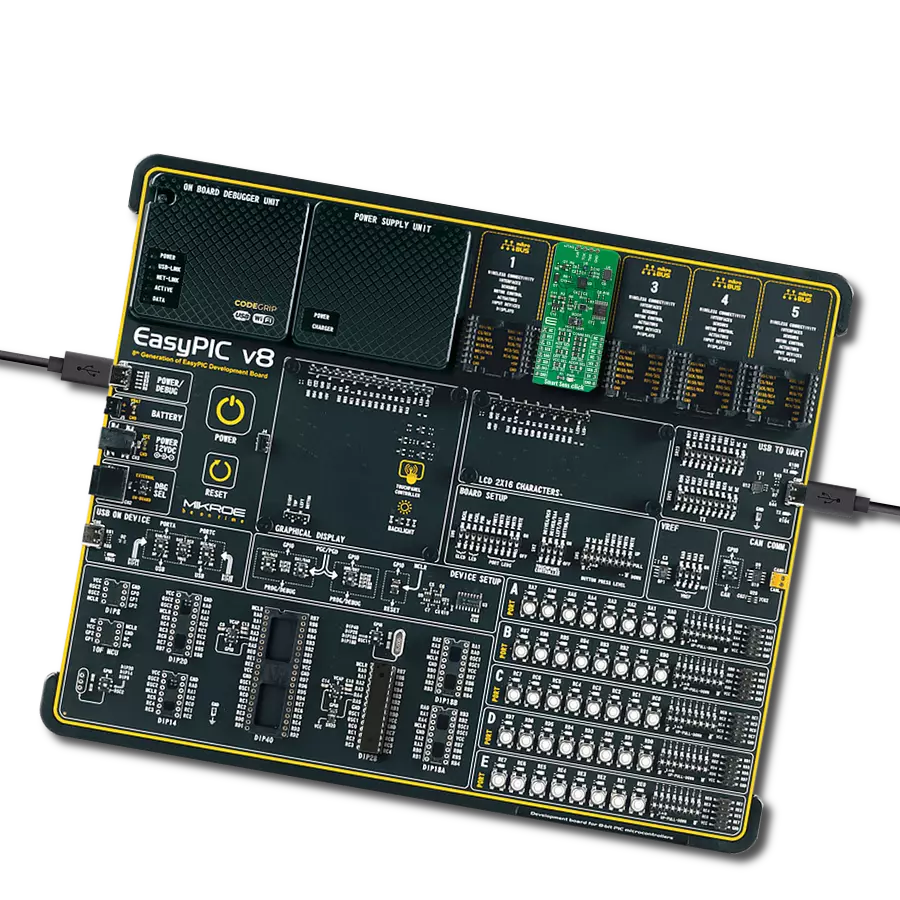
EasyPIC v8
Compiler
NECTO Studio
MCU
PIC18F2515
With a solution like this one designed to determine the acidity or alkalinity of a sample, measured using the pH electrode, you can embark on various applications and activities across different industries and fields
A
A
Hardware Overview
How does it work?
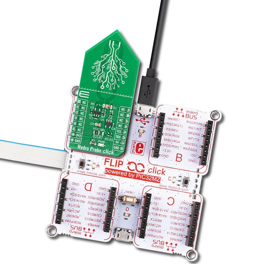
pH 2 Click is based on the MCP607, a low-bias current operational amplifier from Microchip. This Click board™ operation is based on measuring hydrogen ion activity and produces an electrical potential or voltage. An electric potential develops when two liquids of different pH come into contact at opposite sides of a pH electrode thin glass membrane. The pH electrode represents a passive sensor, which means no excitation source (voltage or current) is required. It is classified as a bipolar sensor because its output can swing above and below the reference point. This board is a perfect solution for a wide variety of pH-sensing applications, including water treatment, chemical processing, medical instrumentation, and environmental test systems. pH 2 Click is used to detect the concentration of hydrogen ions in a solution and convert it into a corresponding
usable output signal. Because the pH electrode produces a bipolar signal, the electrode signal is first level shifted by the MCP607, a low bias current Op Amp set up in a unity-gain configuration with configurable reference for its calibration. Second, due to the high impedance of the electrode, another Op Amp inside the MCP607 provides the required high-input impedance buffer. A buffered signal can be then converted to a digital value using the MCP3221, a successive approximation A/D converter with a 12-bit resolution from Microchip using a 2-wire I2C compatible interface, or can be sent directly to an analog pin of the mikroBUS™ socket labeled as AN. The selection can be performed using an onboard SMD switch labeled OUT SEL, placing it in an appropriate position marked as AN or ADC. It is important to note that a pH electrode's sensitivity varies over
temperature. For this reason, it is possible to add the DS18B20, 1-wire thermometer via the DQ terminal to the pH 2 Click, whose temperature can be monitored via the DQ pin on the mikroBUS™ socket. In addition, the user can digitally monitor different statuses in operation through the ST1 and ST2 pins on the mikroBUS™ socket or through visual detection on the STAT1 and STAT2 LEDs. This Click board™ can operate with either 3.3V or 5V logic voltage levels selected via the VCC SEL jumper. This way, both 3.3V and 5V capable MCUs can use the communication lines properly. Also, this Click board™ comes equipped with a library containing easy-to-use functions and an example code that can be used, as a reference, for further development.

Features overview
Development board
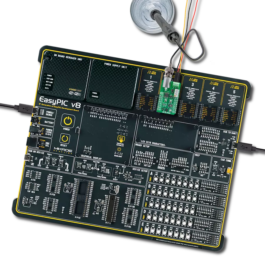
EasyPIC v8 is a development board specially designed for the needs of rapid development of embedded applications. It supports many high pin count 8-bit PIC microcontrollers from Microchip, regardless of their number of pins, and a broad set of unique functions, such as the first-ever embedded debugger/programmer. The development board is well organized and designed so that the end-user has all the necessary elements, such as switches, buttons, indicators, connectors, and others, in one place. Thanks to innovative manufacturing technology, EasyPIC v8 provides a fluid and immersive working experience, allowing access anywhere and under any
circumstances at any time. Each part of the EasyPIC v8 development board contains the components necessary for the most efficient operation of the same board. In addition to the advanced integrated CODEGRIP programmer/debugger module, which offers many valuable programming/debugging options and seamless integration with the Mikroe software environment, the board also includes a clean and regulated power supply module for the development board. It can use a wide range of external power sources, including a battery, an external 12V power supply, and a power source via the USB Type-C (USB-C) connector.
Communication options such as USB-UART, USB DEVICE, and CAN are also included, including the well-established mikroBUS™ standard, two display options (graphical and character-based LCD), and several different DIP sockets. These sockets cover a wide range of 8-bit PIC MCUs, from the smallest PIC MCU devices with only eight up to forty pins. EasyPIC v8 is an integral part of the Mikroe ecosystem for rapid development. Natively supported by Mikroe software tools, it covers many aspects of prototyping and development thanks to a considerable number of different Click boards™ (over a thousand boards), the number of which is growing every day.

Microcontroller Overview
MCU Card / MCU
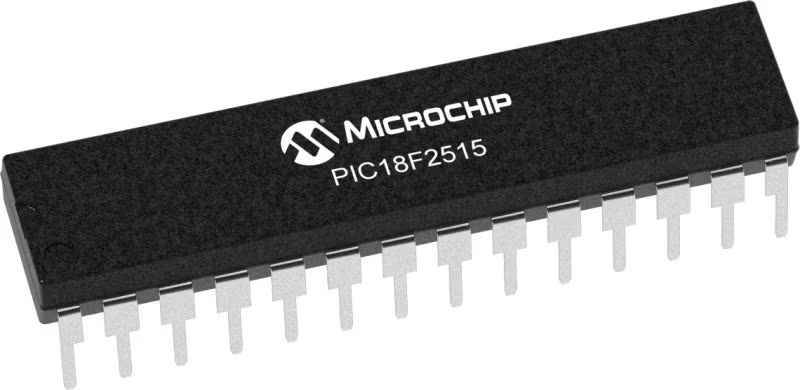
Architecture
PIC
MCU Memory (KB)
48
Silicon Vendor
Microchip
Pin count
28
RAM (Bytes)
3968
You complete me!
Accessories
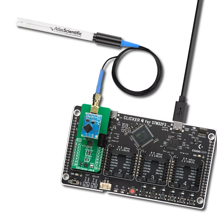
This probe can be used with all pH meters with an input for the BNC connection with a 1m cable. The sensitive part of the probe (in the shape of a ball) is partially protected by a probe's plastic body, which reduces the possibility of mechanical damage. The EPH101 is used to measure the pH value of various liquids (due to the present plastic protection), and it can also be immersed in liquids inflowed in a system). It is stored in a plastic gel bottle with a very long shelf life. A pH (potential of Hydrogen) probe measures the hydrogen ion activity in a liquid. A membrane at the tip of a pH probe permits hydrogen ions from the liquid to be measured to defuse into the outer layer of the membrane while larger ions remain in the solution. The difference in the concentration of hydrogen ions outside the probe vs. inside the pH probe creates a small current proportional to the concentration of hydrogen ions in the measured liquid.

Used MCU Pins
mikroBUS™ mapper
Take a closer look
Click board™ Schematic

Step by step
Project assembly

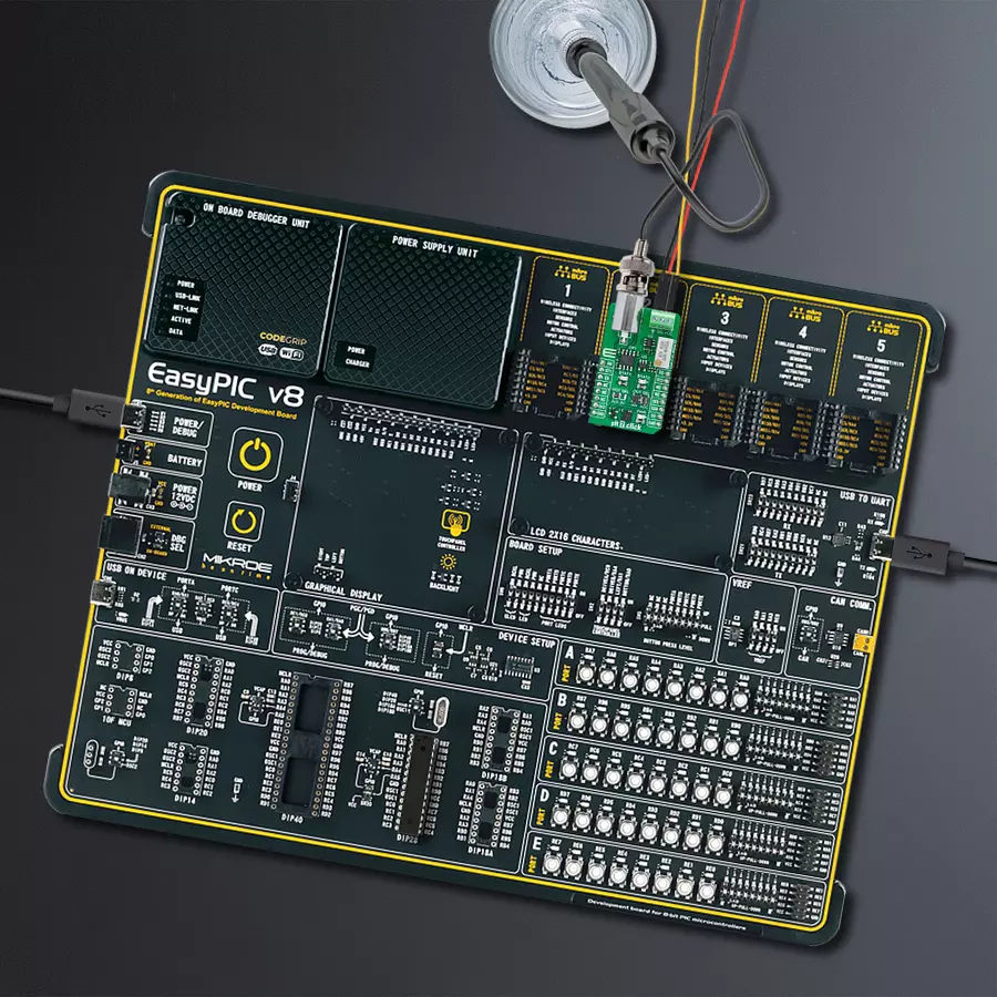
Start by selecting your development board and Click board™. Begin with the EasyPIC v8 as your development board.


Software Support
Library Description
This library contains API for pH 2 Click driver.
Key functions:
ph2_calibrate- Ph 2 calibrate functionph2_calculate_ph- Ph 2 calculate pH value functionph2_calibrate_offset- Ph 2 calibrate offset function
Open Source
Code example
The complete application code and a ready-to-use project are available through the NECTO Studio Package Manager for direct installation in the NECTO Studio. The application code can also be found on the MIKROE GitHub account.
/*!
 * @file main.c
 * @brief pH 2 Click Example.
 *
 * # Description
 * This library contains API for pH 2 Click driver.
 * The library initializes and defines the I2C bus drivers or
 * ADC drivers to read data from pH probe.
 *
 * The demo application is composed of two sections :
 *
 * ## Application Init
 * Initializes the driver and performs offset calibration,
 * as well as calibration in pH-neutral substance.

 *
 * ## Application Task
 * This example demonstrates the use of the pH 2 Click board by
 * reading pH value of the substance where probe is placed.
 *
 * @author Stefan Ilic
 *
 */

#include "board.h"
#include "log.h"
#include "ph2.h"

static ph2_t ph2;   /**< pH 2 Click driver object. */
static log_t logger;    /**< Logger object. */

void application_init ( void )
{
    log_cfg_t log_cfg;  /**< Logger config object. */
    ph2_cfg_t ph2_cfg;  /**< Click config object. */

    /**
     * Logger initialization.
     * Default baud rate: 115200
     * Default log level: LOG_LEVEL_DEBUG
     * @note If USB_UART_RX and USB_UART_TX
     * are defined as HAL_PIN_NC, you will
     * need to define them manually for log to work.
     * See @b LOG_MAP_USB_UART macro definition for detailed explanation.
     */
    LOG_MAP_USB_UART( log_cfg );
    log_init( &logger, &log_cfg );
    log_info( &logger, " Application Init " );

    // Click initialization.
    ph2_cfg_setup( &ph2_cfg );
    PH2_MAP_MIKROBUS( ph2_cfg, MIKROBUS_1 );
    err_t init_flag = ph2_init( &ph2, &ph2_cfg );
    if ( ( ADC_ERROR == init_flag ) || ( I2C_MASTER_ERROR == init_flag ) )
    {
        log_error( &logger, " Communication init." );
        for ( ; ; );
    }

    log_printf( &logger, " ================================ \r\n" );
    log_printf( &logger, "     Performing calibration       \r\n" );
    log_printf( &logger, " ================================ \r\n" );
    log_printf( &logger, " Disconect BNC connector, \r\n" );
    log_printf( &logger, "    short-circuit it, \r\n" );
    log_printf( &logger, " adjust offset potentiometer \r\n" );
    log_printf( &logger, " ================================ \r\n" );
    log_printf( &logger, " STAT1 - turn clockwise \r\n" );
    log_printf( &logger, " STAT2 - turn counter-clockwise \r\n" );
    log_printf( &logger, " ================================ \r\n" );

    ph2_calibrate_offset( &ph2 );

    log_printf( &logger, " Calibration completed \r\n" );
    log_printf( &logger, " ================================ \r\n" );

    log_printf( &logger, " Connect probe back \r\n" );
    log_printf( &logger, " ================================ \r\n" );
    Delay_ms ( 1000 );
    Delay_ms ( 1000 );
    Delay_ms ( 1000 );
    Delay_ms ( 1000 );
    Delay_ms ( 1000 );
    log_printf( &logger, "  Place probe into pH  \r\n" );
    log_printf( &logger, " neutral substance for \r\n" );
    log_printf( &logger, " mid point calibration \r\n" );
    log_printf( &logger, " ================================ \r\n" );
    Delay_ms ( 1000 );
    Delay_ms ( 1000 );
    Delay_ms ( 1000 );
    Delay_ms ( 1000 );
    Delay_ms ( 1000 );
    log_printf( &logger, " Starting calibration  \r\n" );
    log_printf( &logger, " ================================ \r\n" );

    ph2_calibrate( &ph2, 7 );

    log_printf( &logger, " Calibration done!  \r\n" );
    log_printf( &logger, " ================================ \r\n" );

    log_info( &logger, " Application Task " );
    log_printf( &logger, " ================================ \r\n" );
}

void application_task ( void )
{
    float pH_val = 0;
    ph2_calculate_ph( &ph2, &pH_val );
    log_printf( &logger, " pH value: %.3f \r\n", pH_val );
    log_printf( &logger, " ================================ \r\n" );
    Delay_ms ( 1000 );
}

int main ( void )
{
    /* Do not remove this line or clock might not be set correctly. */
    #ifdef PREINIT_SUPPORTED
    preinit();
    #endif

    application_init( );

    for ( ; ; )
    {
        application_task( );
    }

    return 0;
}

// ------------------------------------------------------------------------ END