Determine the distance of the desired target with VL53L5CX and PIC18F26K22
Detect the unexpected

Published Nov 01, 2023
Click board™
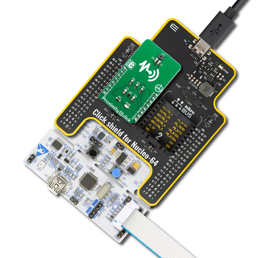
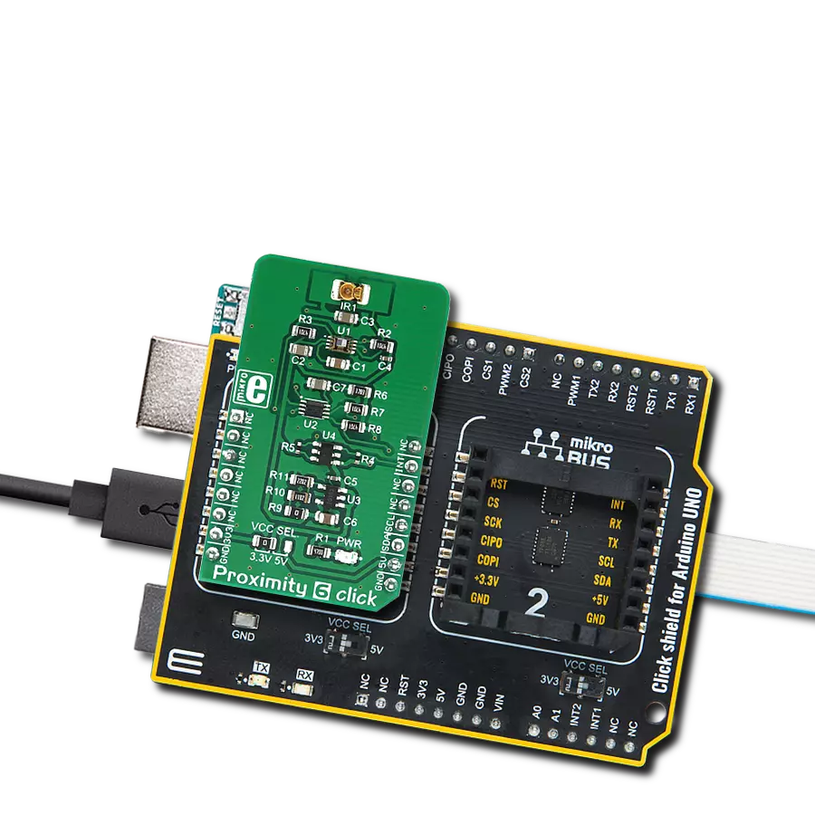
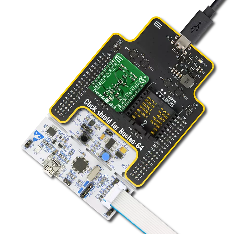
Proximity 16 Click
Dev. board
EasyPIC v8
Compiler
NECTO Studio
MCU
PIC18F26K22
Detect the absence or presence of an object without physical contact
A
A
Hardware Overview
How does it work?
Proximity 16 Click is based on the VL53L5CX, an 8x8 multi-zone Time-of-Flight sensor with wide FoV for each zone from STMicroelectronics. The VL53L5CX offers multi-target detection and distance measurement in each zone up to 4 meters. It integrates a SPAD array, physical infrared filters, and diffractive optical elements to achieve the best-ranging performance in various ambient lighting conditions. Also, with ST’s patented histogram algorithms, the VL53L5CX detects multiple objects within the FoV and ensures immunity to cover glass crosstalk beyond 60cm. Using diffractive optical elements above the vertical cavity surface emitting laser (VCSEL) allows a square field-of-view of 45°x45° (63° diagonal)
to be projected onto the scene, where the receiver lens focuses the light reflection onto a SPAD array. The VL53L5CX can range to 8x8 zones at 15Hz for higher resolution or 4x4 at 60Hz for faster-ranging measurements. Proximity 16 Click communicates with MCU using the standard I2C 2-Wire interface to read data and configure settings, supporting Fast Mode Plus Mode up to 1MHz. Also, this Click board™ provides the ability to use I2C communication in Low-Power mode, which activates via the setting of the LP pin routed to the PWM pin on the mikroBUS™ socket. Besides, it provides an intelligent interrupt function that generates every time a ranging measurement is available, alongside an I2C Reset feature
routed to the RST pin on the mikroBUS™ socket, which resets the sensor I2C communication only. Once the host reads the result, the interrupt is cleared, and the ranging sequence can repeat. This Click board™ can only be operated with a 3.3V logic voltage level. The board must perform appropriate logic voltage level conversion before using MCUs with different logic levels. However, the Click board™ comes equipped with a library containing functions and an example code that can be used as a reference for further development.


Features overview
Development board
EasyPIC v8 is a development board specially designed for the needs of rapid development of embedded applications. It supports many high pin count 8-bit PIC microcontrollers from Microchip, regardless of their number of pins, and a broad set of unique functions, such as the first-ever embedded debugger/programmer. The development board is well organized and designed so that the end-user has all the necessary elements, such as switches, buttons, indicators, connectors, and others, in one place. Thanks to innovative manufacturing technology, EasyPIC v8 provides a fluid and immersive working experience, allowing access anywhere and under any
circumstances at any time. Each part of the EasyPIC v8 development board contains the components necessary for the most efficient operation of the same board. In addition to the advanced integrated CODEGRIP programmer/debugger module, which offers many valuable programming/debugging options and seamless integration with the Mikroe software environment, the board also includes a clean and regulated power supply module for the development board. It can use a wide range of external power sources, including a battery, an external 12V power supply, and a power source via the USB Type-C (USB-C) connector.
Communication options such as USB-UART, USB DEVICE, and CAN are also included, including the well-established mikroBUS™ standard, two display options (graphical and character-based LCD), and several different DIP sockets. These sockets cover a wide range of 8-bit PIC MCUs, from the smallest PIC MCU devices with only eight up to forty pins. EasyPIC v8 is an integral part of the Mikroe ecosystem for rapid development. Natively supported by Mikroe software tools, it covers many aspects of prototyping and development thanks to a considerable number of different Click boards™ (over a thousand boards), the number of which is growing every day.

Microcontroller Overview
MCU Card / MCU
Architecture
PIC
MCU Memory (KB)
64
Silicon Vendor
Microchip
Pin count
28
RAM (Bytes)
3896
Used MCU Pins
mikroBUS™ mapper
Take a closer look
Click board™ Schematic

Step by step
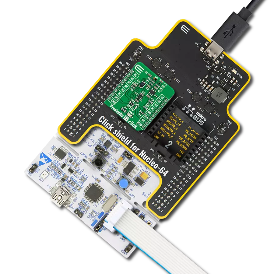
Project assembly

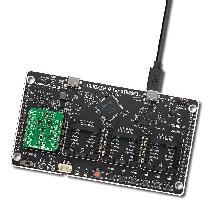
Start by selecting your development board and Click board™. Begin with the EasyPIC v8 as your development board.


Track your results in real time
Application Output
1. Application Output - In Debug mode, the 'Application Output' window enables real-time data monitoring, offering direct insight into execution results. Ensure proper data display by configuring the environment correctly using the provided tutorial.

2. UART Terminal - Use the UART Terminal to monitor data transmission via a USB to UART converter, allowing direct communication between the Click board™ and your development system. Configure the baud rate and other serial settings according to your project's requirements to ensure proper functionality. For step-by-step setup instructions, refer to the provided tutorial.

3. Plot Output - The Plot feature offers a powerful way to visualize real-time sensor data, enabling trend analysis, debugging, and comparison of multiple data points. To set it up correctly, follow the provided tutorial, which includes a step-by-step example of using the Plot feature to display Click board™ readings. To use the Plot feature in your code, use the function: plot(*insert_graph_name*, variable_name);. This is a general format, and it is up to the user to replace 'insert_graph_name' with the actual graph name and 'variable_name' with the parameter to be displayed.

Software Support
Library Description
This library contains API for Proximity 16 Click driver.
Key functions:
proximity16_get_int_pinThis function returns the INT pin logic state.proximity16_get_resolutionThis function gets the current resolution (4x4 or 8x8).proximity16_get_ranging_dataThis function gets the ranging data, using the selected output and the resolution.
Open Source
Code example
The complete application code and a ready-to-use project are available through the NECTO Studio Package Manager for direct installation in the NECTO Studio. The application code can also be found on the MIKROE GitHub account.
/*!
 * @file main.c
 * @brief Proximity 16 Click example
 *
 * # Description
 * This example demonstrates the use of Proximity 16 Click board by reading and displaying
 * 8x8 zones measurements on the USB UART.
 *
 * The demo application is composed of two sections :
 *
 * ## Application Init
 * Initializes the driver and performs the Click default configuration.
 *
 * ## Application Task
 * Reads all zone measurements approximately every 500ms and logs them to the USB UART as an 8x8 map.
 * The silicon temperature measurement in degrees Celsius is also displayed.
 *
 * @author Stefan Filipovic
 *
 */

#include "board.h"
#include "log.h"
#include "proximity16.h"

static proximity16_t proximity16;
static log_t logger;

void application_init ( void )
{
    log_cfg_t log_cfg;  /**< Logger config object. */
    proximity16_cfg_t proximity16_cfg;  /**< Click config object. */

    /**
     * Logger initialization.
     * Default baud rate: 115200
     * Default log level: LOG_LEVEL_DEBUG
     * @note If USB_UART_RX and USB_UART_TX
     * are defined as HAL_PIN_NC, you will
     * need to define them manually for log to work.
     * See @b LOG_MAP_USB_UART macro definition for detailed explanation.
     */
    LOG_MAP_USB_UART( log_cfg );
    log_init( &logger, &log_cfg );
    log_info( &logger, " Application Init " );

    // Click initialization.
    proximity16_cfg_setup( &proximity16_cfg );
    PROXIMITY16_MAP_MIKROBUS( proximity16_cfg, MIKROBUS_1 );
    if ( I2C_MASTER_ERROR == proximity16_init( &proximity16, &proximity16_cfg ) )
    {
        log_error( &logger, " Communication init." );
        for ( ; ; );
    }

    if ( PROXIMITY16_ERROR == proximity16_default_cfg ( &proximity16 ) )
    {
        log_error( &logger, " Default configuration." );
        for ( ; ; );
    }

    log_info( &logger, " Application Task " );
}

void application_task ( void )
{
    if ( !proximity16_get_int_pin ( &proximity16 ) )
    {
        proximity16_results_data_t results;
        uint8_t resolution, map_side;
        err_t error_flag = proximity16_get_resolution ( &proximity16, &resolution );
        error_flag |= proximity16_get_ranging_data ( &proximity16, &results );
        if ( PROXIMITY16_OK == error_flag )
        {
            map_side = ( PROXIMITY16_RESOLUTION_4X4 == resolution ) ? 4 : 8;
            log_printf ( &logger, "\r\n %ux%u MAP (mm):\r\n", ( uint16_t ) map_side, ( uint16_t ) map_side );
            for ( uint16_t cnt = 1; cnt <= resolution; cnt++ )
            {
                log_printf ( &logger, " %u\t", results.distance_mm[ cnt - 1 ] );
                if ( 0 == ( cnt % map_side ) )
                {
                    log_printf ( &logger, "\r\n" );
                }
            }
            log_printf ( &logger, " Silicon temperature : %d degC\r\n", ( int16_t ) results.silicon_temp_degc );
        }
    }
}

int main ( void )
{
    /* Do not remove this line or clock might not be set correctly. */
    #ifdef PREINIT_SUPPORTED
    preinit();
    #endif

    application_init( );

    for ( ; ; )
    {
        application_task( );
    }

    return 0;
}

// ------------------------------------------------------------------------ END