Experience RTC excellence today with PT7C4311 and PIC18F2585
Timing is everything: Elevate your projects with our RTC solution

Published Nov 01, 2023
Click board™
RTC 21 Click
Dev. board
EasyPIC v8
Compiler
NECTO Studio
MCU
PIC18F2585
Integrate efficient real-time clock into your solution for precise event timing and seamless synchronization
A
A
Hardware Overview
How does it work?
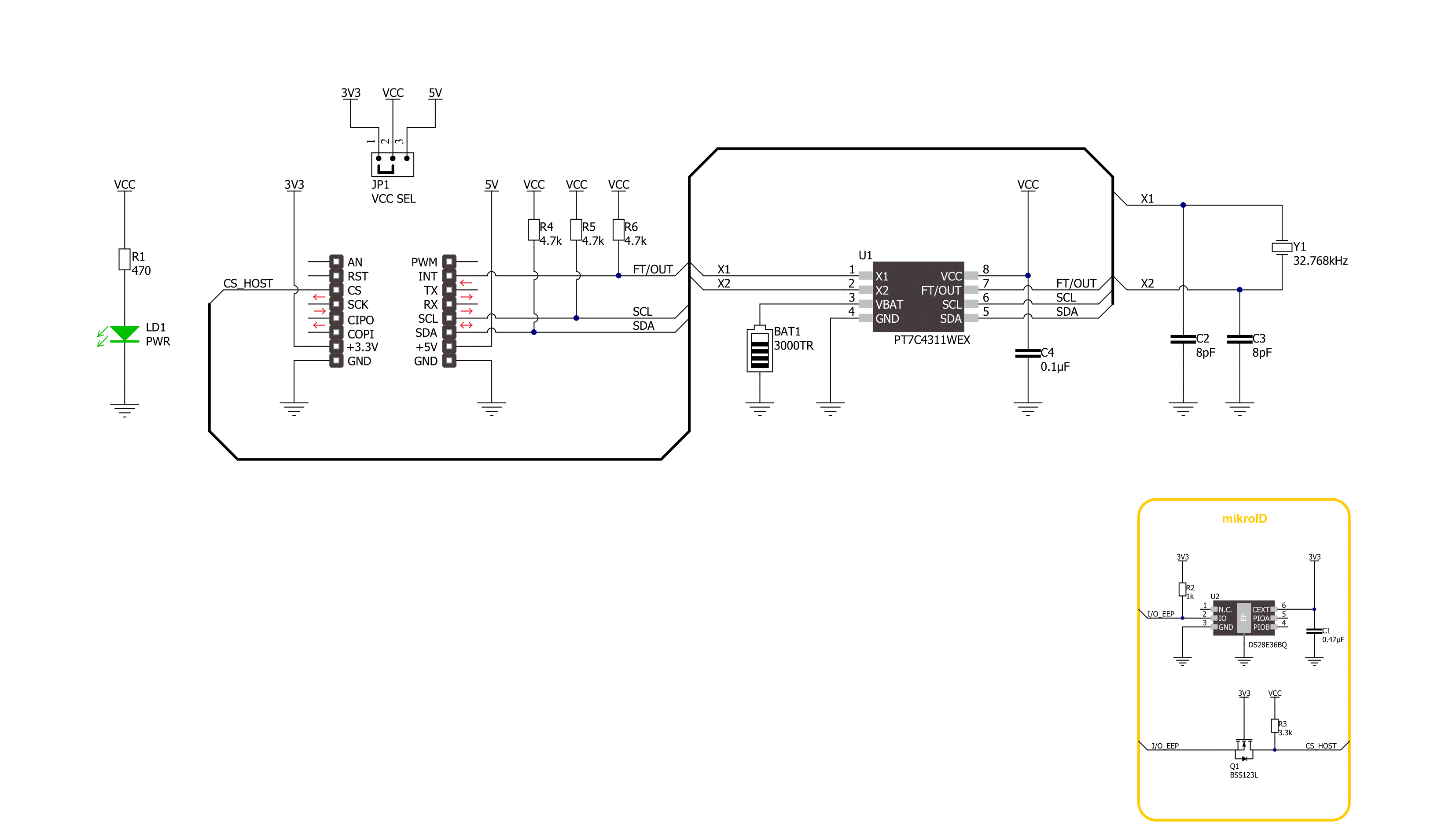
RTC 21 Click is based on the PT7C4311, an ultra-low power, real-time clock (RTC) time-keeping device from Diodes Incorporated. The PT7C4311 is configured to transmit calendar and time data to the MCU (24-hour format) based on a 32.768kHz quartz crystal and comes with 56 bytes of general-purpose RAM. It reads and writes clock/calendar data from and to the MCU in units ranging from seconds to the last two digits of the calendar year, providing seconds, minutes, hours, dates, days, months, year, and century information.
The end-of-the-month date is automatically adjusted for months with fewer than 31 days, including corrections for the leap year until 2100. This Click board™ communicates with MCU using the standard I2C 2-Wire interface to read data and configure settings, supporting a Fast Mode operation up to 400kHz. It also incorporates one open-drain output labeled FT, which can be used as a frequency test signal (512Hz square-wave password for frequency test purposes) or as a register-configurable output DC level when
square-wave is disabled. The PT7C4311 also includes an automatic backup switchover circuit, allowing it to be used with a single-button cell battery for an extended period. This Click board™ can operate with either 3.3V or 5V logic voltage levels selected via the VCC SEL jumper. This way, both 3.3V and 5V capable MCUs can use the communication lines properly. Also, this Click board™ comes equipped with a library containing easy-to-use functions and an example code that can be used for further development.


Features overview
Development board
EasyPIC v8 is a development board specially designed for the needs of rapid development of embedded applications. It supports many high pin count 8-bit PIC microcontrollers from Microchip, regardless of their number of pins, and a broad set of unique functions, such as the first-ever embedded debugger/programmer. The development board is well organized and designed so that the end-user has all the necessary elements, such as switches, buttons, indicators, connectors, and others, in one place. Thanks to innovative manufacturing technology, EasyPIC v8 provides a fluid and immersive working experience, allowing access anywhere and under any
circumstances at any time. Each part of the EasyPIC v8 development board contains the components necessary for the most efficient operation of the same board. In addition to the advanced integrated CODEGRIP programmer/debugger module, which offers many valuable programming/debugging options and seamless integration with the Mikroe software environment, the board also includes a clean and regulated power supply module for the development board. It can use a wide range of external power sources, including a battery, an external 12V power supply, and a power source via the USB Type-C (USB-C) connector.
Communication options such as USB-UART, USB DEVICE, and CAN are also included, including the well-established mikroBUS™ standard, two display options (graphical and character-based LCD), and several different DIP sockets. These sockets cover a wide range of 8-bit PIC MCUs, from the smallest PIC MCU devices with only eight up to forty pins. EasyPIC v8 is an integral part of the Mikroe ecosystem for rapid development. Natively supported by Mikroe software tools, it covers many aspects of prototyping and development thanks to a considerable number of different Click boards™ (over a thousand boards), the number of which is growing every day.

Microcontroller Overview
MCU Card / MCU
Architecture
PIC
MCU Memory (KB)
48
Silicon Vendor
Microchip
Pin count
28
RAM (Bytes)
3328
Used MCU Pins
mikroBUS™ mapper
Take a closer look
Click board™ Schematic
Step by step
Project assembly

Start by selecting your development board and Click board™. Begin with the EasyPIC v8 as your development board.


Software Support
Library Description
This library contains API for RTC 21 Click driver.
Key functions:
rtc21_set_time- This function sets the starting time values - second, minute and hourrtc21_set_date- This function sets the starting date values - day of week, day, month and yearrtc21_read_time- This function reads the current time values - second, minute and hour
Open Source
Code example
The complete application code and a ready-to-use project are available through the NECTO Studio Package Manager for direct installation in the NECTO Studio. The application code can also be found on the MIKROE GitHub account.
/*!
 * @file main.c
 * @brief RTC 21 Click example
 *
 * # Description
 * This example demonstrates the use of RTC 21 Click board by reading and displaying
 * the time and date values.
 *
 * The demo application is composed of two sections :
 *
 * ## Application Init
 * Initializes the driver and logger and then sets the starting time and date.
 *
 * ## Application Task
 * Reads and displays on the USB UART the current time and date values once per second.
 *
 * @author Stefan Filipovic
 *
 */

#include "board.h"
#include "log.h"
#include "rtc21.h"

static rtc21_t rtc21;
static log_t logger;
static rtc21_time_t time;
static rtc21_date_t date;

/**
 * @brief RTC 21 get day of week name function.
 * @details This function returns the name of day of the week as a string.
 * @param[in] ctx : Click context object.
 * See #rtc21_t object definition for detailed explanation.
 * @param[in] day_of_week : Day of week decimal value.
 * @return Name of day as a string.
 * @note None.
 */
static uint8_t *rtc21_get_day_of_week_name ( uint8_t day_of_week );

void application_init ( void )
{
    log_cfg_t log_cfg;  /**< Logger config object. */
    rtc21_cfg_t rtc21_cfg;  /**< Click config object. */

    /**
     * Logger initialization.
     * Default baud rate: 115200
     * Default log level: LOG_LEVEL_DEBUG
     * @note If USB_UART_RX and USB_UART_TX
     * are defined as HAL_PIN_NC, you will
     * need to define them manually for log to work.
     * See @b LOG_MAP_USB_UART macro definition for detailed explanation.
     */
    LOG_MAP_USB_UART( log_cfg );
    log_init( &logger, &log_cfg );
    log_info( &logger, " Application Init " );

    // Click initialization.
    rtc21_cfg_setup( &rtc21_cfg );
    RTC21_MAP_MIKROBUS( rtc21_cfg, MIKROBUS_1 );
    if ( I2C_MASTER_ERROR == rtc21_init( &rtc21, &rtc21_cfg ) )
    {
        log_error( &logger, " Communication init." );
        for ( ; ; );
    }

    time.hour = 23;
    time.minute = 59;
    time.second = 50;
    if ( RTC21_OK == rtc21_set_time ( &rtc21, &time ) )
    {
        log_printf( &logger, " Set time: %.2u:%.2u:%.2u\r\n",
                    ( uint16_t ) time.hour, ( uint16_t ) time.minute, ( uint16_t ) time.second );
    }
    date.day_of_week = RTC21_SATURDAY;
    date.day = 31;
    date.month = 12;
    date.year = 22;
    if ( RTC21_OK == rtc21_set_date ( &rtc21, &date ) )
    {
        log_printf( &logger, " Set date: %s, %.2u.%.2u.20%.2u.\r\n",
                    rtc21_get_day_of_week_name ( date.day_of_week ),
                    ( uint16_t ) date.day, ( uint16_t ) date.month, ( uint16_t ) date.year );
    }
    Delay_ms ( 100 );

    log_info( &logger, " Application Task " );
}

void application_task ( void )
{
    if ( RTC21_OK == rtc21_read_time ( &rtc21, &time ) )
    {
        log_printf( &logger, " Time: %.2u:%.2u:%.2u\r\n",
                    ( uint16_t ) time.hour, ( uint16_t ) time.minute, ( uint16_t ) time.second );
    }
    if ( RTC21_OK == rtc21_read_date ( &rtc21, &date ) )
    {
        log_printf( &logger, " Date: %s, %.2u.%.2u.20%.2u.\r\n",
                    rtc21_get_day_of_week_name ( date.day_of_week ),
                    ( uint16_t ) date.day, ( uint16_t ) date.month, ( uint16_t ) date.year );
    }
    Delay_ms ( 1000 );
}

int main ( void )
{
    /* Do not remove this line or clock might not be set correctly. */
    #ifdef PREINIT_SUPPORTED
    preinit();
    #endif

    application_init( );

    for ( ; ; )
    {
        application_task( );
    }

    return 0;
}

static uint8_t *rtc21_get_day_of_week_name ( uint8_t day_of_week )
{
    switch ( day_of_week )
    {
        case RTC21_MONDAY:
        {
            return "Monday";
        }
        case RTC21_TUESDAY:
        {
            return "Tuesday";
        }
        case RTC21_WEDNESDAY:
        {
            return "Wednesday";
        }
        case RTC21_THURSDAY:
        {
            return "Thursday";
        }
        case RTC21_FRIDAY:
        {
            return "Friday";
        }
        case RTC21_SATURDAY:
        {
            return "Saturday";
        }
        case RTC21_SUNDAY:
        {
            return "Sunday";
        }
        default:
        {
            return "Unknown";
        }
    }
}

// ------------------------------------------------------------------------ END


