Enhance your lighting experience with LED1202 and PIC18F2458
Shine brighter, last longer!
Published Dec 29, 2023
Click board™
LED Driver 19 Click
Dev. board
EasyPIC v7
Compiler
NECTO Studio
MCU
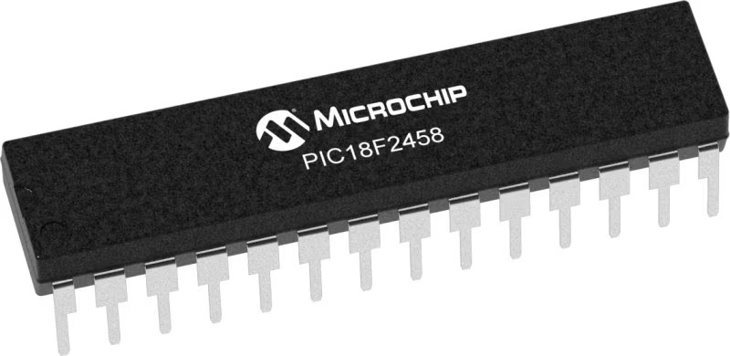
PIC18F2458
Upgrade your lighting experience with our dependable LED driver solution, meticulously crafted for enhanced brightness, extended longevity, and optimal efficiency, because your light deserves to shine its brightest for years to come.
A
A
Hardware Overview
How does it work?
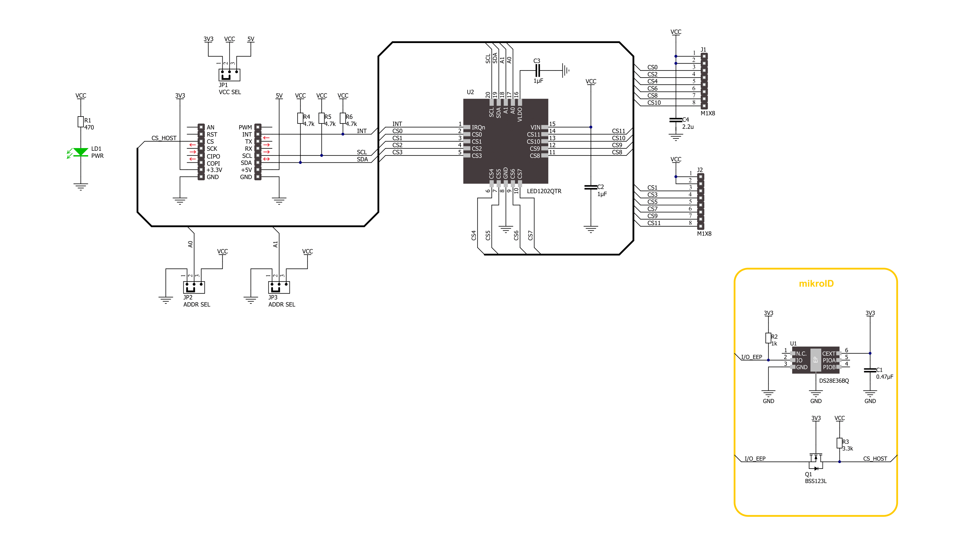
LED Driver 19 Click is based on the LED1202, a 12-channel low quiescent current LED driver from STMicroelectronics. Its internal non-volatile memory can store up to 8 different patterns, each with a particular output configuration, thus enabling automatic sequencing without MCU intervention. Each channel has an output PWM dimming frequency of 220Hz in a 12-bit resolution. Analog dimming range is from 1 up to 20mA, in 256 steps per channel, and common to all patterns. In addition, using one of the PWM or
analog modes, you can use both of them to achieve full control of LED brightness. This LED driver also features a built-in open LED detection and thermal shutdown function that turns OFF all output drivers during an over-temperature condition. The LED Driver 19 Click uses a standard I2C 2-Wire interface to communicate with the host MCU. The I2C address can be selected via two ADDR SEL jumpers, where 0 is selected by default on both. The LED1202 driver can generate an interrupt on the INT pin if a fault or condition
occurs; by that, it means an open LED, overtemperature, pattern end, and frame start. The INT pin informs the system about those statuses with active LOW. This Click board™ can operate with either 3.3V or 5V logic voltage levels selected via the VCC SEL jumper. This way, both 3.3V and 5V capable MCUs can use the communication lines properly. Also, this Click board™ comes equipped with a library containing easy-to-use functions and an example code that can be used for further development.

Features overview
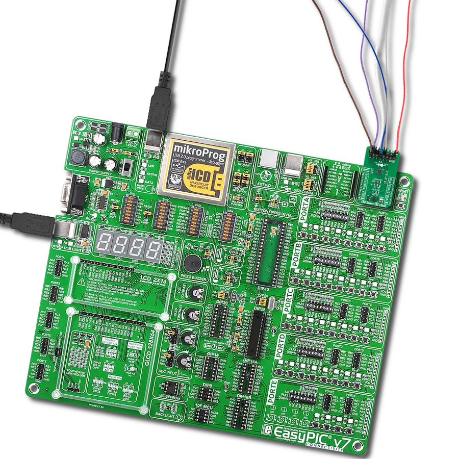
Development board
EasyPIC v7 is the seventh generation of PIC development boards specially designed to develop embedded applications rapidly. It supports a wide range of 8-bit PIC microcontrollers from Microchip and has a broad set of unique functions, such as a powerful onboard mikroProg programmer and In-Circuit debugger over USB-B. The development board is well organized and designed so that the end-user has all the necessary elements in one place, such as switches, buttons, indicators, connectors, and others. With four different connectors for each port, EasyPIC v7 allows you to connect accessory boards, sensors, and custom electronics more efficiently than ever. Each part of
the EasyPIC v7 development board contains the components necessary for the most efficient operation of the same board. An integrated mikroProg, a fast USB 2.0 programmer with mikroICD hardware In-Circuit Debugger, offers many valuable programming/debugging options and seamless integration with the Mikroe software environment. Besides it also includes a clean and regulated power supply block for the development board. It can use various external power sources, including an external 12V power supply, 7-23V AC or 9-32V DC via DC connector/screw terminals, and a power source via the USB Type-B (USB-B) connector. Communication options such as
USB-UART and RS-232 are also included, alongside the well-established mikroBUS™ standard, three display options (7-segment, graphical, and character-based LCD), and several different DIP sockets. These sockets cover a wide range of 8-bit PIC MCUs, from PIC10F, PIC12F, PIC16F, PIC16Enh, PIC18F, PIC18FJ, and PIC18FK families. EasyPIC v7 is an integral part of the Mikroe ecosystem for rapid development. Natively supported by Mikroe software tools, it covers many aspects of prototyping and development thanks to a considerable number of different Click boards™ (over a thousand boards), the number of which is growing every day.

Microcontroller Overview
MCU Card / MCU
Architecture
PIC
MCU Memory (KB)
24
Silicon Vendor
Microchip
Pin count
28
RAM (Bytes)
2048
Used MCU Pins
mikroBUS™ mapper
Take a closer look
Click board™ Schematic
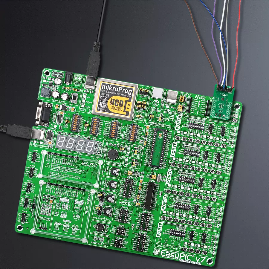
Step by step
Project assembly

Start by selecting your development board and Click board™. Begin with the EasyPIC v7 as your development board.


Software Support
Library Description
This library contains API for LED Driver 19 Click driver.
Key functions:
leddriver19_sw_reset- LED Driver 19 software reset function.leddriver19_enable_channels- LED Driver 19 enables channels function.leddriver19_set_pattern_pwm- LED Driver 19 set pattern PWM value function.
Open Source
Code example
The complete application code and a ready-to-use project are available through the NECTO Studio Package Manager for direct installation in the NECTO Studio. The application code can also be found on the MIKROE GitHub account.
/*!
 * @file main.c
 * @brief LED Driver 19 Click example
 *
 * # Description
 * This library contains API for LED Driver 19 Click driver.
 * The library initializes and defines the I2C bus drivers to
 * write the default configuration for a PWM output value
 * of the out pins.
 *
 * The demo application is composed of two sections :
 *
 * ## Application Init
 * Initializes the driver and performs default configuration, sets the device
 * in output enabled mode and checks communication by reading device ID.
 *
 * ## Application Task
 * This example demonstrates the use of the LED Driver 19 Click board by
 * changing PWM values of all channels from maximum to minimum turning
 * LEDs on and off in the process.
 *
 * @author Stefan Ilic
 *
 */

#include "board.h"
#include "log.h"
#include "leddriver19.h"

static leddriver19_t leddriver19;
static log_t logger;

void application_init ( void )
{
    log_cfg_t log_cfg;  /**< Logger config object. */
    leddriver19_cfg_t leddriver19_cfg;  /**< Click config object. */

    /**
     * Logger initialization.
     * Default baud rate: 115200
     * Default log level: LOG_LEVEL_DEBUG
     * @note If USB_UART_RX and USB_UART_TX
     * are defined as HAL_PIN_NC, you will
     * need to define them manually for log to work.
     * See @b LOG_MAP_USB_UART macro definition for detailed explanation.
     */
    LOG_MAP_USB_UART( log_cfg );
    log_init( &logger, &log_cfg );
    log_info( &logger, " Application Init " );

    // Click initialization.
    leddriver19_cfg_setup( &leddriver19_cfg );
    LEDDRIVER19_MAP_MIKROBUS( leddriver19_cfg, MIKROBUS_1 );
    if ( I2C_MASTER_ERROR == leddriver19_init( &leddriver19, &leddriver19_cfg ) )
    {
        log_error( &logger, " Communication init." );
        for ( ; ; );
    }

    uint8_t device_id;

    leddriver19_read_reg( &leddriver19, LEDDRIVER19_REG_DEVICE_ID, &device_id );
    if ( LEDDRIVER19_DEVICE_ID != device_id )
    {
        log_error( &logger, " Communication error." );
        for ( ; ; );
    }

    if ( LEDDRIVER19_ERROR == leddriver19_default_cfg ( &leddriver19 ) )
    {
        log_error( &logger, " Default configuration." );
        for ( ; ; );
    }

    log_info( &logger, " Application Task " );
}

void application_task ( void )
{
    for ( uint8_t n_cnt = LEDDRIVER19_CH_SEL_0; n_cnt <= LEDDRIVER19_CH_SEL_11; n_cnt++ )
    {
        leddriver19_set_pattern_pwm( &leddriver19, LEDDRIVER19_PATSEL_0, n_cnt, 100  );
        Delay_ms ( 100 );
    }
    Delay_ms ( 1000 );

    for ( uint8_t n_cnt = LEDDRIVER19_CH_SEL_0; n_cnt <= LEDDRIVER19_CH_SEL_11; n_cnt++ )
    {
        leddriver19_set_pattern_pwm( &leddriver19, LEDDRIVER19_PATSEL_0, n_cnt, 0  );
        Delay_ms ( 100 );
    }
    Delay_ms ( 1000 );
}

int main ( void )
{
    /* Do not remove this line or clock might not be set correctly. */
    #ifdef PREINIT_SUPPORTED
    preinit();
    #endif

    application_init( );

    for ( ; ; )
    {
        application_task( );
    }

    return 0;
}

// ------------------------------------------------------------------------ END


