Ensure the air you breathe is of the highest quality using SGP30 and PIC18F57Q43
See the unseen, breathe the pure
Published Feb 13, 2024
Click board™
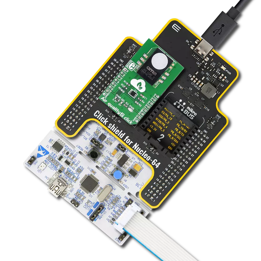
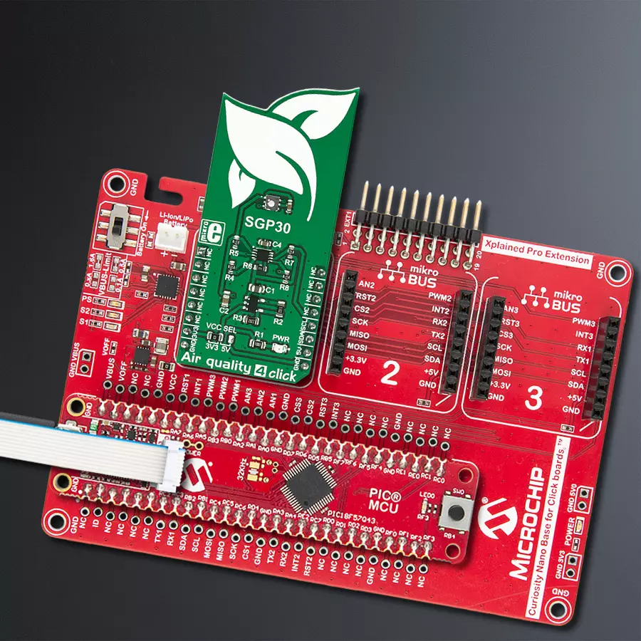
Air quality 4 Click
Dev. board
Curiosity Nano with PIC18F57Q43
Compiler
NECTO Studio
MCU
PIC18F57Q43
From homes to workplaces, our air quality monitor solution seamlessly integrates into any environment, providing real-time insights for a safer, cleaner lifestyle
A
A
Hardware Overview
How does it work?
Air Quality 4 Click is based on the SGP30 from Sensirion, a multi-pixel gas sensor for indoor applications. This sensor is a system of several metal-oxide sensing elements on a chip (pixels), used to measure and process readings of various gasses in the air and output them in the form of two complementary air quality readings - Total Volatile Organic Compounds (TVOC) [ppb] and CO2 equivalent signal [ppm]. The traditional metal-oxide (MOX) sensors suffer from sensitivity and responsiveness degradation after siloxane exposure. Siloxanes are compounds commonly found in the air, negatively affecting the MOX sensors. To overcome this problem, the SGP30 sensors use the advanced MOXSens® Technology, which provides unmatched robustness against siloxane contamination. This results in unprecedented long-term stability and accuracy. The SGP30 uses a dynamic baseline compensation algorithm and calibration parameters to record TVOC and CO2eq properties accurately. These baseline values of the compensation algorithm
can be stored externally and read back into the device with the appropriate I2C commands and can be used in the event of power down or restart. For the first 15 seconds after the I2C initialization command, the sensor is in an initialization phase of collecting sensor measurements and baseline compensation data. When the measurement command is attempted, it will return fixed values of 400 ppm CO2eq and 0 ppb TVOC. The device also allows air humidity corrections over the results for both the compensated and raw values. However, an absolute humidity sensor should be used for obtaining the humidity reading. Readings from SHT click or similar humidity-measuring devices can be used for this purpose. The appropriate I2C command will store the value in the on-chip memory and perform the corrections accordingly. Additional components on Air Quality 4 clicks are used to provide necessary voltage levels for the SGP30 sensor IC. This sensor has a common voltage level of 1.8V, so to provide proper communication with 3.3V and 5V capable MCUs, a
small LDO voltage regulator has to be used, along with the level shifter, which provides the required logic voltage levels. The SPX3819M5, a small 500mA LDO voltage regulator, provides a power supply of 1.8V for the SGP30. The PCA9306 dual bidirectional I2C bus and SMBus voltage level shifter are used for the level shifting. This level shifter IC allows shifting (converting) the I2C signal levels to the voltage level selected by the VCC SEL onboard SMD jumper. This allows 3.3V and 5V capable MCUs to be interfaced with the Air quality 4 Click. More detailed information about all the available I2C commands can be found in the SGP30 datasheet. However, all the functions and commands necessary to perform air quality readings and functions used to calculate H2 and Ethanol concentration levels are contained within the Air Quality 4 click libraries provided with this click board™. Their usage is demonstrated in the included example application, which can be used as a reference for a custom application design.


Features overview
Development board
PIC18F57Q43 Curiosity Nano evaluation kit is a cutting-edge hardware platform designed to evaluate microcontrollers within the PIC18-Q43 family. Central to its design is the inclusion of the powerful PIC18F57Q43 microcontroller (MCU), offering advanced functionalities and robust performance. Key features of this evaluation kit include a yellow user LED and a responsive
mechanical user switch, providing seamless interaction and testing. The provision for a 32.768kHz crystal footprint ensures precision timing capabilities. With an onboard debugger boasting a green power and status LED, programming and debugging become intuitive and efficient. Further enhancing its utility is the Virtual serial port (CDC) and a debug GPIO channel (DGI
GPIO), offering extensive connectivity options. Powered via USB, this kit boasts an adjustable target voltage feature facilitated by the MIC5353 LDO regulator, ensuring stable operation with an output voltage ranging from 1.8V to 5.1V, with a maximum output current of 500mA, subject to ambient temperature and voltage constraints.

Microcontroller Overview
MCU Card / MCU

Architecture
PIC
MCU Memory (KB)
128
Silicon Vendor
Microchip
Pin count
48
RAM (Bytes)
8196
You complete me!
Accessories
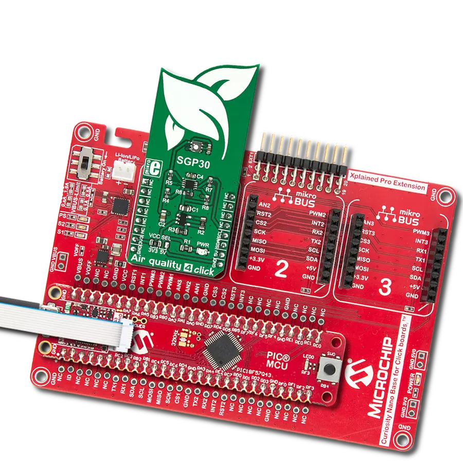
Curiosity Nano Base for Click boards is a versatile hardware extension platform created to streamline the integration between Curiosity Nano kits and extension boards, tailored explicitly for the mikroBUS™-standardized Click boards and Xplained Pro extension boards. This innovative base board (shield) offers seamless connectivity and expansion possibilities, simplifying experimentation and development. Key features include USB power compatibility from the Curiosity Nano kit, alongside an alternative external power input option for enhanced flexibility. The onboard Li-Ion/LiPo charger and management circuit ensure smooth operation for battery-powered applications, simplifying usage and management. Moreover, the base incorporates a fixed 3.3V PSU dedicated to target and mikroBUS™ power rails, alongside a fixed 5.0V boost converter catering to 5V power rails of mikroBUS™ sockets, providing stable power delivery for various connected devices.

Used MCU Pins
mikroBUS™ mapper
Take a closer look
Click board™ Schematic

Step by step
Project assembly

Start by selecting your development board and Click board™. Begin with the Curiosity Nano with PIC18F57Q43 as your development board.


Track your results in real time
Application Output
1. Application Output - In Debug mode, the 'Application Output' window enables real-time data monitoring, offering direct insight into execution results. Ensure proper data display by configuring the environment correctly using the provided tutorial.

2. UART Terminal - Use the UART Terminal to monitor data transmission via a USB to UART converter, allowing direct communication between the Click board™ and your development system. Configure the baud rate and other serial settings according to your project's requirements to ensure proper functionality. For step-by-step setup instructions, refer to the provided tutorial.

3. Plot Output - The Plot feature offers a powerful way to visualize real-time sensor data, enabling trend analysis, debugging, and comparison of multiple data points. To set it up correctly, follow the provided tutorial, which includes a step-by-step example of using the Plot feature to display Click board™ readings. To use the Plot feature in your code, use the function: plot(*insert_graph_name*, variable_name);. This is a general format, and it is up to the user to replace 'insert_graph_name' with the actual graph name and 'variable_name' with the parameter to be displayed.

Software Support
Library Description
This library contains API for Air Quality 4 Click driver.
Key functions:
air_quality4_soft_reset- This function calls general reset witch resets all states on the chipair_quality4_get_co2_and_tvoc- This function writes 2 bytes CO2 data and 2 bytes TVOC data without CRC dataair_quality4_get_h2_and_ehtoh- This function writes 2 bytes H2 data and 2 bytes EthOH data without CRC data
Open Source
Code example
The complete application code and a ready-to-use project are available through the NECTO Studio Package Manager for direct installation in the NECTO Studio. The application code can also be found on the MIKROE GitHub account.
/*!
 * \file
 * \brief AirQuality4 Click example
 *
 * # Description
 * This application measures the amount of substances in air and air quality and logs the results.
 *
 * The demo application is composed of two sections :
 *
 * ## Application Init
 * nitializes Click driver and gets ID data.
 *
 * ## Application Task
 * Performs measurements of air concentracion for H2, EthOH, CO2 and TVOC data.
 * Results of measurement shows on USBUART.
 *
 * \author MikroE Team
 *
 */
// ------------------------------------------------------------------- INCLUDES

#include "board.h"
#include "log.h"
#include "airquality4.h"

// ------------------------------------------------------------------ VARIABLES

static airquality4_t airquality4;
static log_t logger;
static uint8_t buffer_data[ 6 ];
static uint16_t data_buffer[ 2 ];

// ------------------------------------------------------ APPLICATION FUNCTIONS

void application_init ( void )
{
    log_cfg_t log_cfg;
    airquality4_cfg_t cfg;

    /**
     * Logger initialization.
     * Default baud rate: 115200
     * Default log level: LOG_LEVEL_DEBUG
     * @note If USB_UART_RX and USB_UART_TX
     * are defined as HAL_PIN_NC, you will
     * need to define them manually for log to work.
     * See @b LOG_MAP_USB_UART macro definition for detailed explanation.
     */
    LOG_MAP_USB_UART( log_cfg );
    log_init( &logger, &log_cfg );
    log_info( &logger, "---- Application Init ----" );

    //  Click initialization.

    airquality4_cfg_setup( &cfg );
    AIRQUALITY4_MAP_MIKROBUS( cfg, MIKROBUS_1 );
    airquality4_init( &airquality4, &cfg );
    airquality4_default_cfg( &airquality4 );
}

void application_task ( void )
{
    air_quality4_get_h2_and_ethon( &airquality4, data_buffer);

    log_printf( &logger, "H2 value is: %u\n", data_buffer[ 0 ] );
    log_printf( &logger, "EthOH value is:  %u\n", data_buffer[ 1 ] );

    air_quality4_set_baseline( &airquality4 );
    air_quality4_get_co2_and_tvoc( &airquality4, &data_buffer[ 0 ] );

    log_printf( &logger, "CO2 value is: %u\n", data_buffer[ 0 ] );
    log_printf( &logger, "TVOC value is: %u\n\n", data_buffer[ 1 ] );

    Delay_ms ( 1000 );
}

int main ( void )
{
    /* Do not remove this line or clock might not be set correctly. */
    #ifdef PREINIT_SUPPORTED
    preinit();
    #endif

    application_init( );

    for ( ; ; )
    {
        application_task( );
    }

    return 0;
}


// ------------------------------------------------------------------------ END
Additional Support
Resources
Category:Gas