Navigate the spectrum of colors with confidence using APDS-9250 and PIC18F57Q43
A world of colors, one sensing solution

Published Feb 13, 2024
Click board™
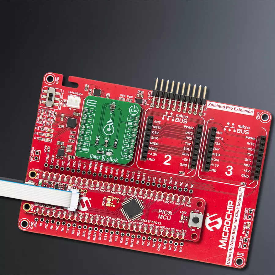
Color 9 Click
Dev. board
Curiosity Nano with PIC18F57Q43
Compiler
NECTO Studio
MCU
PIC18F57Q43
With our color sensing solution, you can confidently address applications such as color matching, printing, and textile production, where precise color detection is paramount to success
A
A
Hardware Overview
How does it work?
Color 9 Click is based on the APDS-9250, an integrated color sensor IC from Broadcom. This highly advanced four-channel color sensing device incorporates an IR blocking filter, that is used to block a portion of light in the IR spectrum, which can interfere with the readings of three independent photo-diodes, used to sense red, green and blue components of the light. However, it features an additional IR photo-sensing element, which is used to detect the intensity in the IR range. The IR measurement value can be used as a compensation parameter for the accurate color calculation. The color intensity sensing is roughly matched to the sensitivity of the human eye, so the sensor is the most sensitive in the range between 500nm and 600nm. The datasheet of the APDS-9250 offers an intensity over the wavelength diagram, so an accurate color calculation can be made in respect to the variable sensitivity of the sensor over the light wavelength. There are four independent A/D converters which are used to
digitize the color intensity in 18-bit resolution. The color and IR conversion results are available at the output registers in MSB/LSB format. Color 9 click communicates with the host MCU over the I2C interface, with its pin routed to the appropriate SCL and SDA pins of the mikroBUS™. The powerful interrupt engine allows more optimized firmware for the controller (MCU) to be written. The interrupt engine allows 16-bit values for the upper and lower threshold levels to be defined, as well as the persistence interval during which the event has occurred, before the interrupt is triggered, and more. Also, the user has the possibility to select which channel is included in the interrupt event detection.The APDS-9250 requires a very low number of external components. It requires only pull-up resistors for the I2C bus lines and the INT pin, which is an open-drain interrupt line. To allow for the best performance and most accurate measurements, the surface of the board and especially the
sensor IC itself, should always stay clean and without scratches, as dirt and moisture can after the light penetration through the filters. In addition, the manufacturer recommends that the angle of incidence stays less than 10° since the sensor IC has an aperture angle (beam width) of nearly 90°. If the angle of incidence is greater than advised, the filter shifting might occur, introducing distortion and affecting the measurement results. The spectral filters of this sensor are specialized for working with the broadband source of light, and measurement of the narrowband light sources should not be performed by this sensor. This Click board™ can be operated only with a 3.3V logic voltage level. The board must perform appropriate logic voltage level conversion before using MCUs with different logic levels. Also, it comes equipped with a library containing functions and an example code that can be used as a reference for further development.


Features overview
Development board
PIC18F57Q43 Curiosity Nano evaluation kit is a cutting-edge hardware platform designed to evaluate microcontrollers within the PIC18-Q43 family. Central to its design is the inclusion of the powerful PIC18F57Q43 microcontroller (MCU), offering advanced functionalities and robust performance. Key features of this evaluation kit include a yellow user LED and a responsive
mechanical user switch, providing seamless interaction and testing. The provision for a 32.768kHz crystal footprint ensures precision timing capabilities. With an onboard debugger boasting a green power and status LED, programming and debugging become intuitive and efficient. Further enhancing its utility is the Virtual serial port (CDC) and a debug GPIO channel (DGI
GPIO), offering extensive connectivity options. Powered via USB, this kit boasts an adjustable target voltage feature facilitated by the MIC5353 LDO regulator, ensuring stable operation with an output voltage ranging from 1.8V to 5.1V, with a maximum output current of 500mA, subject to ambient temperature and voltage constraints.

Microcontroller Overview
MCU Card / MCU

Architecture
PIC
MCU Memory (KB)
128
Silicon Vendor
Microchip
Pin count
48
RAM (Bytes)
8196
You complete me!
Accessories
Curiosity Nano Base for Click boards is a versatile hardware extension platform created to streamline the integration between Curiosity Nano kits and extension boards, tailored explicitly for the mikroBUS™-standardized Click boards and Xplained Pro extension boards. This innovative base board (shield) offers seamless connectivity and expansion possibilities, simplifying experimentation and development. Key features include USB power compatibility from the Curiosity Nano kit, alongside an alternative external power input option for enhanced flexibility. The onboard Li-Ion/LiPo charger and management circuit ensure smooth operation for battery-powered applications, simplifying usage and management. Moreover, the base incorporates a fixed 3.3V PSU dedicated to target and mikroBUS™ power rails, alongside a fixed 5.0V boost converter catering to 5V power rails of mikroBUS™ sockets, providing stable power delivery for various connected devices.

Used MCU Pins
mikroBUS™ mapper
Take a closer look
Click board™ Schematic

Step by step
Project assembly

Start by selecting your development board and Click board™. Begin with the Curiosity Nano with PIC18F57Q43 as your development board.


Track your results in real time
Application Output
1. Application Output - In Debug mode, the 'Application Output' window enables real-time data monitoring, offering direct insight into execution results. Ensure proper data display by configuring the environment correctly using the provided tutorial.

2. UART Terminal - Use the UART Terminal to monitor data transmission via a USB to UART converter, allowing direct communication between the Click board™ and your development system. Configure the baud rate and other serial settings according to your project's requirements to ensure proper functionality. For step-by-step setup instructions, refer to the provided tutorial.

3. Plot Output - The Plot feature offers a powerful way to visualize real-time sensor data, enabling trend analysis, debugging, and comparison of multiple data points. To set it up correctly, follow the provided tutorial, which includes a step-by-step example of using the Plot feature to display Click board™ readings. To use the Plot feature in your code, use the function: plot(*insert_graph_name*, variable_name);. This is a general format, and it is up to the user to replace 'insert_graph_name' with the actual graph name and 'variable_name' with the parameter to be displayed.

Software Support
Library Description
This library contains API for Color 9 Click driver.
Key functions:
color9_get_green- This function gets Green measurement readingcolor9_get_blue- This function gets Blue measurement readingcolor9_get_red- This function gets Red measurement reading.
Open Source
Code example
The complete application code and a ready-to-use project are available through the NECTO Studio Package Manager for direct installation in the NECTO Studio. The application code can also be found on the MIKROE GitHub account.
/*!
 * \file
 * \brief Color9 Click example
 *
 * # Description
 * This application collects data from the sensor and logs green, blue and red
 * measurement readings.
 *
 * The demo application is composed of two sections :
 *
 * ## Application Init
 * Initialize the driver and test if the sensor is
 * present. If the ID read from the sensor is correct
 * execute the initialization procedure.
 *
 * ## Application Task
 * Wait for the color data to be available then read the data
 * and send it to the serial port.
 *
 *
 * \author MikroE Team
 *
 */
// ------------------------------------------------------------------- INCLUDES

#include "board.h"
#include "log.h"
#include "color9.h"

// ------------------------------------------------------------------ VARIABLES

static color9_t color9;
static log_t logger;

// ------------------------------------------------------ APPLICATION FUNCTIONS

void application_init ( void )
{
    log_cfg_t log_cfg;
    color9_cfg_t cfg;

    uint8_t id;

    /**
     * Logger initialization.
     * Default baud rate: 115200
     * Default log level: LOG_LEVEL_DEBUG
     * @note If USB_UART_RX and USB_UART_TX
     * are defined as HAL_PIN_NC, you will
     * need to define them manually for log to work.
     * See @b LOG_MAP_USB_UART macro definition for detailed explanation.
     */
    LOG_MAP_USB_UART( log_cfg );
    log_init( &logger, &log_cfg );
    log_info( &logger, "---- Application Init ----" );

    //  Click initialization.

    color9_cfg_setup( &cfg );
    COLOR9_MAP_MIKROBUS( cfg, MIKROBUS_1 );
    color9_init( &color9, &cfg );

    id = color9_read( &color9, COLOR9_PART_ID );

    if ( id == 0xB2 )
    {
        log_printf( &logger, "Register id 0x%x\r\n", id );
        color9_meas_rate( &color9, COLOR9_LS_MEAS_BITWIDTH_13, COLOR9_LS_MEAS_RATE_1000ms );
        color9_reg_ctrl( &color9, COLOR9_MAIN_CTRL_CS_MODE | COLOR9_MAIN_CTRL_LS_EN );
    }
    else
    {
        log_printf( &logger, "Error\r\n" );
        while ( 1 );
    }
}

void application_task ( void )
{
    uint8_t conv_complete;
    uint32_t measurement_data;

    conv_complete = color9_get_status_reg( &color9 );

    if ( conv_complete & 0x08 )
    {
        conv_complete = 0;
        measurement_data = color9_get_Ir( &color9 );
        log_printf( &logger, "Ir: %d\r\n", measurement_data );

        measurement_data = color9_get_green( &color9 );
        log_printf(&logger, "Green: %d\r\n", measurement_data);

        measurement_data = color9_get_blue( &color9 );
        log_printf(&logger, "Blue: %d\r\n", measurement_data);

        measurement_data = color9_get_red( &color9 );
        log_printf(&logger, "Red: %d\r\n", measurement_data);
    }
}

int main ( void )
{
    /* Do not remove this line or clock might not be set correctly. */
    #ifdef PREINIT_SUPPORTED
    preinit();
    #endif

    application_init( );

    for ( ; ; )
    {
        application_task( );
    }

    return 0;
}


// ------------------------------------------------------------------------ END
Additional Support
Resources
Category:Optical


