Sense and adapt to various ambient light conditions with VEML3235SL and STM32L073RZ
Brighter, smarter, better

Published Feb 26, 2024
Click board™
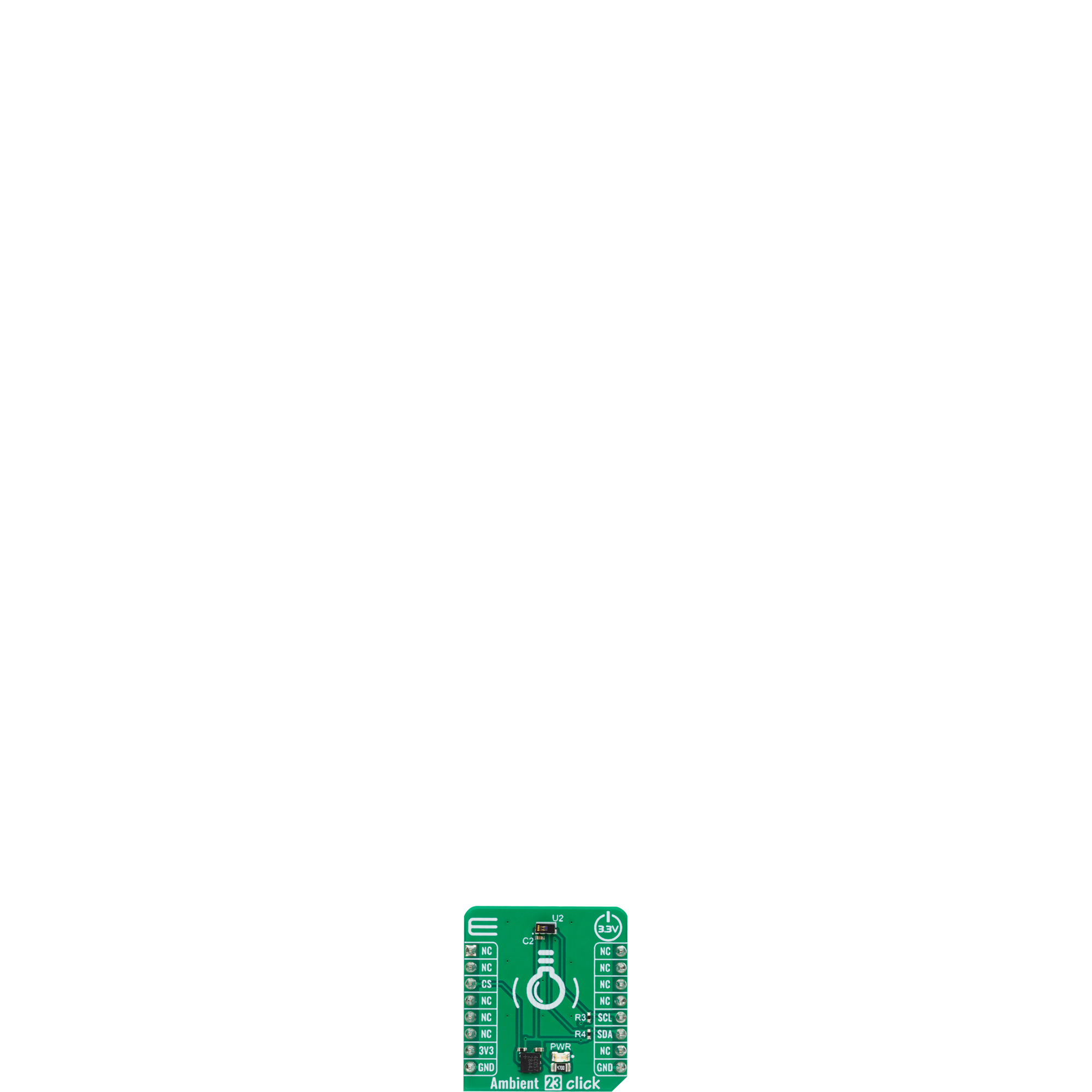
Ambient 23 Click
Dev. board
Nucleo-64 with STM32L073RZ MCU
Compiler
NECTO Studio
MCU
STM32L073RZ
Upgrade your lighting control with our cutting-edge technology that measures and optimizes visible ambient light intensity.
A
A
Hardware Overview
How does it work?
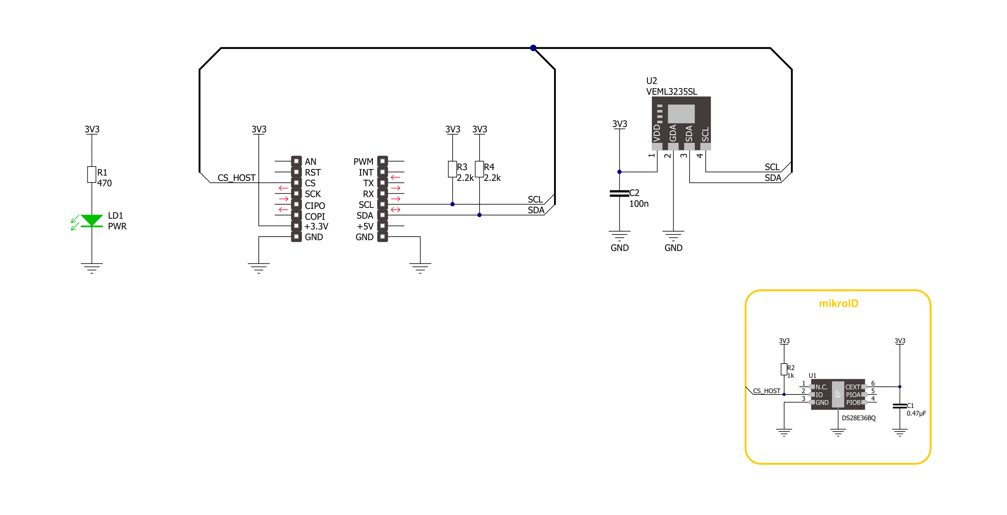
Ambient 23 Click is based on the VEML3235SL, a high-accuracy light-to-digital converter from Vishay Semiconductors that transforms light intensity into a digital output signal. The VEML3235SL includes a highly sensitive photodiode, low noise amplifier, and 16-bit A/D converter and supports an easy-to-use serial communication interface. The ambient light read-out is available as a digital value, and the built-in photodiode response is near the human eye's. The 16-bit dynamic range for ambient light detection is from 0.0021 to 17.867lx, with resolution down to 0.0021lx/counts. The sensor's remarkable sensitivity
of 0.0021lx enables it to operate even when placed behind dark cover glass that significantly blocks light. Still, it can also function behind transparent cover glass, as it can handle high illumination levels up to approximately 18klx without saturation. This Click board™ communicates with the host MCU using the standard I2C 2-Wire interface supporting Standard Mode operation with a clock frequency of 100kHz and Fast Mode up to 400kHz. All operations are controlled by the command register, allowing users to easily program the operation setting and latch the light data from VEML3235SL. In addition to its
outstanding temperature compensation capabilities, the VEML3235SL also offers the added benefit of software shutdown mode control, allowing for random measurements, such as once per second, during which the sensor can be switched to shutdown mode to minimize power consumption. This Click board™ can be operated only with a 3.3V logic voltage level. The board must perform appropriate logic voltage level conversion before using MCUs with different logic levels. Also, it comes equipped with a library containing functions and an example code that can be used as a reference for further development.

Features overview
Development board
Nucleo-64 with STM32L073RZ MCU offers a cost-effective and adaptable platform for developers to explore new ideas and prototype their designs. This board harnesses the versatility of the STM32 microcontroller, enabling users to select the optimal balance of performance and power consumption for their projects. It accommodates the STM32 microcontroller in the LQFP64 package and includes essential components such as a user LED, which doubles as an ARDUINO® signal, alongside user and reset push-buttons, and a 32.768kHz crystal oscillator for precise timing operations. Designed with expansion and flexibility in mind, the Nucleo-64 board features an ARDUINO® Uno V3 expansion connector and ST morpho extension pin
headers, granting complete access to the STM32's I/Os for comprehensive project integration. Power supply options are adaptable, supporting ST-LINK USB VBUS or external power sources, ensuring adaptability in various development environments. The board also has an on-board ST-LINK debugger/programmer with USB re-enumeration capability, simplifying the programming and debugging process. Moreover, the board is designed to simplify advanced development with its external SMPS for efficient Vcore logic supply, support for USB Device full speed or USB SNK/UFP full speed, and built-in cryptographic features, enhancing both the power efficiency and security of projects. Additional connectivity is
provided through dedicated connectors for external SMPS experimentation, a USB connector for the ST-LINK, and a MIPI® debug connector, expanding the possibilities for hardware interfacing and experimentation. Developers will find extensive support through comprehensive free software libraries and examples, courtesy of the STM32Cube MCU Package. This, combined with compatibility with a wide array of Integrated Development Environments (IDEs), including IAR Embedded Workbench®, MDK-ARM, and STM32CubeIDE, ensures a smooth and efficient development experience, allowing users to fully leverage the capabilities of the Nucleo-64 board in their projects.

Microcontroller Overview
MCU Card / MCU

Architecture
ARM Cortex-M0
MCU Memory (KB)
192
Silicon Vendor
STMicroelectronics
Pin count
64
RAM (Bytes)
20480
You complete me!
Accessories
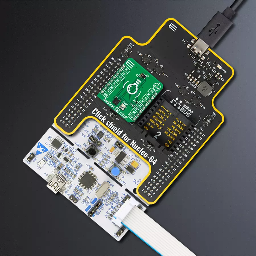
Click Shield for Nucleo-64 comes equipped with two proprietary mikroBUS™ sockets, allowing all the Click board™ devices to be interfaced with the STM32 Nucleo-64 board with no effort. This way, Mikroe allows its users to add any functionality from our ever-growing range of Click boards™, such as WiFi, GSM, GPS, Bluetooth, ZigBee, environmental sensors, LEDs, speech recognition, motor control, movement sensors, and many more. More than 1537 Click boards™, which can be stacked and integrated, are at your disposal. The STM32 Nucleo-64 boards are based on the microcontrollers in 64-pin packages, a 32-bit MCU with an ARM Cortex M4 processor operating at 84MHz, 512Kb Flash, and 96KB SRAM, divided into two regions where the top section represents the ST-Link/V2 debugger and programmer while the bottom section of the board is an actual development board. These boards are controlled and powered conveniently through a USB connection to program and efficiently debug the Nucleo-64 board out of the box, with an additional USB cable connected to the USB mini port on the board. Most of the STM32 microcontroller pins are brought to the IO pins on the left and right edge of the board, which are then connected to two existing mikroBUS™ sockets. This Click Shield also has several switches that perform functions such as selecting the logic levels of analog signals on mikroBUS™ sockets and selecting logic voltage levels of the mikroBUS™ sockets themselves. Besides, the user is offered the possibility of using any Click board™ with the help of existing bidirectional level-shifting voltage translators, regardless of whether the Click board™ operates at a 3.3V or 5V logic voltage level. Once you connect the STM32 Nucleo-64 board with our Click Shield for Nucleo-64, you can access hundreds of Click boards™, working with 3.3V or 5V logic voltage levels.

Used MCU Pins
mikroBUS™ mapper
Take a closer look
Click board™ Schematic
Step by step
Project assembly
Start by selecting your development board and Click board™. Begin with the Nucleo-64 with STM32L073RZ MCU as your development board.


Track your results in real time
Application Output
1. Application Output - In Debug mode, the 'Application Output' window enables real-time data monitoring, offering direct insight into execution results. Ensure proper data display by configuring the environment correctly using the provided tutorial.

2. UART Terminal - Use the UART Terminal to monitor data transmission via a USB to UART converter, allowing direct communication between the Click board™ and your development system. Configure the baud rate and other serial settings according to your project's requirements to ensure proper functionality. For step-by-step setup instructions, refer to the provided tutorial.

3. Plot Output - The Plot feature offers a powerful way to visualize real-time sensor data, enabling trend analysis, debugging, and comparison of multiple data points. To set it up correctly, follow the provided tutorial, which includes a step-by-step example of using the Plot feature to display Click board™ readings. To use the Plot feature in your code, use the function: plot(*insert_graph_name*, variable_name);. This is a general format, and it is up to the user to replace 'insert_graph_name' with the actual graph name and 'variable_name' with the parameter to be displayed.

Software Support
Library Description
This library contains API for Ambient 23 Click driver.
Key functions:
ambient23_reg_read- Ambient 23 register reading function.ambient23_calculate_res- Ambient 23 get conversion data function.ambient23_read_light_data- Ambient 23 get light data function.
Open Source
Code example
The complete application code and a ready-to-use project are available through the NECTO Studio Package Manager for direct installation in the NECTO Studio. The application code can also be found on the MIKROE GitHub account.
/*!
 * @file main.c
 * @brief Ambient 23 Click example
 *
 * # Description
 * This example demonstrates the use of Ambient 23 Click board by measuring
 * the ambient light level in Lux.
 *
 * The demo application is composed of two sections :
 *
 * ## Application Init
 * Initializes the driver, checks communication by reading part ID
 * and performs the Click default configuration.
 *
 * ## Application Task
 * Measuring ambient light level by reading data from the Ambient 23 Click board
 * and displaying it using UART Serial terminal.
 *
 * @author Stefan Ilic
 *
 */

#include "board.h"
#include "log.h"
#include "ambient23.h"

static ambient23_t ambient23;
static log_t logger;

void application_init ( void )
{
    log_cfg_t log_cfg;  /**< Logger config object. */
    ambient23_cfg_t ambient23_cfg;  /**< Click config object. */

    /**
     * Logger initialization.
     * Default baud rate: 115200
     * Default log level: LOG_LEVEL_DEBUG
     * @note If USB_UART_RX and USB_UART_TX
     * are defined as HAL_PIN_NC, you will
     * need to define them manually for log to work.
     * See @b LOG_MAP_USB_UART macro definition for detailed explanation.
     */
    LOG_MAP_USB_UART( log_cfg );
    log_init( &logger, &log_cfg );
    log_info( &logger, " Application Init " );

    // Click initialization.
    ambient23_cfg_setup( &ambient23_cfg );
    AMBIENT23_MAP_MIKROBUS( ambient23_cfg, MIKROBUS_1 );
    if ( I2C_MASTER_ERROR == ambient23_init( &ambient23, &ambient23_cfg ) )
    {
        log_error( &logger, " Communication init." );
        for ( ; ; );
    }

    uint16_t part_id = 0;
    ambient23_reg_read( &ambient23, AMBIENT23_REG_DEVICE_ID, &part_id );
    if ( AMBIENT23_PART_ID != ( uint8_t ) part_id )
    {
        log_error( &logger, " Communication error." );
        for ( ; ; );
    }

    if ( AMBIENT23_ERROR == ambient23_default_cfg ( &ambient23 ) )
    {
        log_error( &logger, " Default configuration." );
        for ( ; ; );
    }

    log_info( &logger, " Application Task " );
}

void application_task ( void )
{
    float data_tmp;

    ambient23_read_light_data( &ambient23, &data_tmp );
    log_printf( &logger, "Data: %.2f lux\r\n", data_tmp );
    Delay_ms ( 1000 );
}

int main ( void )
{
    /* Do not remove this line or clock might not be set correctly. */
    #ifdef PREINIT_SUPPORTED
    preinit();
    #endif

    application_init( );

    for ( ; ; )
    {
        application_task( );
    }

    return 0;
}

// ------------------------------------------------------------------------ END
Additional Support
Resources
Category:Optical


