Experience pH measurement at its finest with pH EZO and PIC18F57Q43
Your go-to expert for precise pH readings, every time
Published Feb 13, 2024
Click board™
pH Click
Dev. board
Curiosity Nano with PIC18F57Q43
Compiler
NECTO Studio
MCU
PIC18F57Q43
Count on our pH meter for reliable pH monitoring in any environment or application.
A
A
Hardware Overview
How does it work?
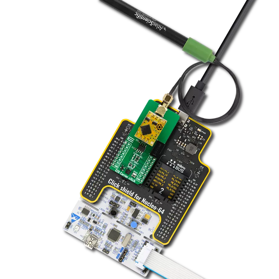
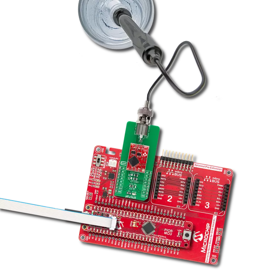
pH Click is based on the pH EZO™, a 6th-generation embedded pH circuit that offers the highest level of stability and accuracy from AtlasScientific. With an easy-to-use UART data protocol (with additional I2C serial interface), simple command structure, and flexible calibration protocol that supports single-point, two-point, or three-point calibration, this Click board™ works well with any off-the-shelf pH probe. It has temperature-dependent or independent readings with a full range of pH readings from 0.001 to 14.000. The pH EZO™ circuit is characterized by great sensitivity that gives its accuracy. When electrical noise interferes with the pH readings, it is common to see rapidly fluctuating readings or readings that are consistently off. To verify that electrical noise is causing inaccurate readings, place the pH probe in a cup of water by itself. The pH readings should
stabilize quickly, confirming that electrical noise was the issue. This Click board™ uses the UART communication interface as its default communication protocol that supports all standard baud rates up to 115.200 but also provides the possibility of using the I2C serial interface. The selection can be performed by positioning SMD jumpers labeled COMM SEL to an appropriate position. Note that all jumpers must be placed on the same side, or the Click board™ may become unresponsive. This Click Board™ uses the UART communication interface as its default communication protocol that supports all standard baud rates up to 115.200 but also provides the possibility of using the I2C serial interface. The selection can be performed by positioning SMD jumpers labeled COMM SEL to an appropriate position. Note that all jumpers must be placed on the same side, or the Click board™ may become
unresponsive. Also, the pH EZO™ circuit contains an LED indicator that informs the user about the current state of the pH circuit at any time with a specified color. The green color indicates Standby Mode, the yellow color indicates sent pH data, and the blue indicates pH data being read. Besides, there is a purple color that signals a change in the Baud rate, a red color that represents an invalid command given by the user, and a white color that the LED flashes when a device is connected to the circuit. This Click board™ can operate with either 3.3V or 5V logic voltage levels selected via the VCC SEL jumper. This way, both 3.3V and 5V capable MCUs can use the communication lines properly. Also, this Click board™ comes equipped with a library containing easy-to-use functions and an example code that can be used as a reference for further development.

Features overview
Development board
PIC18F57Q43 Curiosity Nano evaluation kit is a cutting-edge hardware platform designed to evaluate microcontrollers within the PIC18-Q43 family. Central to its design is the inclusion of the powerful PIC18F57Q43 microcontroller (MCU), offering advanced functionalities and robust performance. Key features of this evaluation kit include a yellow user LED and a responsive
mechanical user switch, providing seamless interaction and testing. The provision for a 32.768kHz crystal footprint ensures precision timing capabilities. With an onboard debugger boasting a green power and status LED, programming and debugging become intuitive and efficient. Further enhancing its utility is the Virtual serial port (CDC) and a debug GPIO channel (DGI
GPIO), offering extensive connectivity options. Powered via USB, this kit boasts an adjustable target voltage feature facilitated by the MIC5353 LDO regulator, ensuring stable operation with an output voltage ranging from 1.8V to 5.1V, with a maximum output current of 500mA, subject to ambient temperature and voltage constraints.

Microcontroller Overview
MCU Card / MCU

Architecture
PIC
MCU Memory (KB)
128
Silicon Vendor
Microchip
Pin count
48
RAM (Bytes)
8196
You complete me!
Accessories
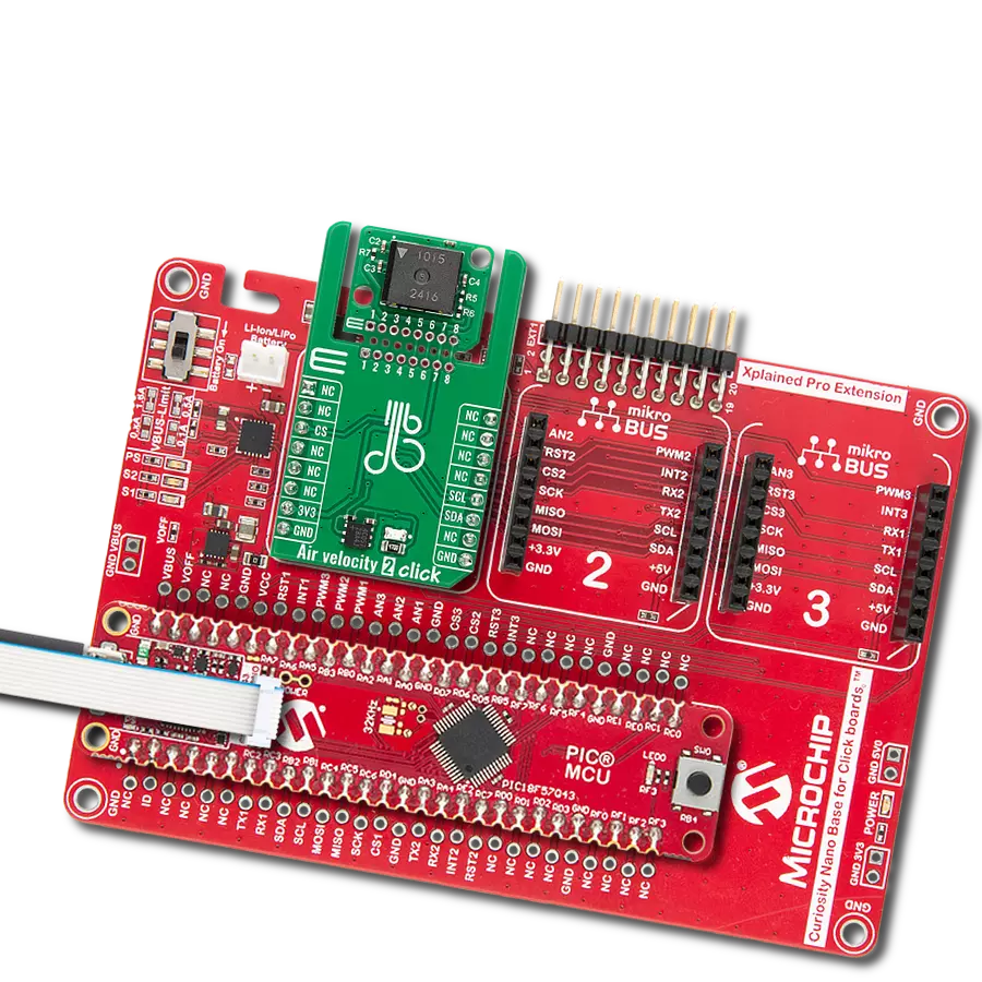
Curiosity Nano Base for Click boards is a versatile hardware extension platform created to streamline the integration between Curiosity Nano kits and extension boards, tailored explicitly for the mikroBUS™-standardized Click boards and Xplained Pro extension boards. This innovative base board (shield) offers seamless connectivity and expansion possibilities, simplifying experimentation and development. Key features include USB power compatibility from the Curiosity Nano kit, alongside an alternative external power input option for enhanced flexibility. The onboard Li-Ion/LiPo charger and management circuit ensure smooth operation for battery-powered applications, simplifying usage and management. Moreover, the base incorporates a fixed 3.3V PSU dedicated to target and mikroBUS™ power rails, alongside a fixed 5.0V boost converter catering to 5V power rails of mikroBUS™ sockets, providing stable power delivery for various connected devices.

This probe can be used with all pH meters with an input for the BNC connection with a 1m cable. The sensitive part of the probe (in the shape of a ball) is partially protected by a probe's plastic body, which reduces the possibility of mechanical damage. The EPH101 is used to measure the pH value of various liquids (due to the present plastic protection), and it can also be immersed in liquids inflowed in a system). It is stored in a plastic gel bottle with a very long shelf life. A pH (potential of Hydrogen) probe measures the hydrogen ion activity in a liquid. A membrane at the tip of a pH probe permits hydrogen ions from the liquid to be measured to defuse into the outer layer of the membrane while larger ions remain in the solution. The difference in the concentration of hydrogen ions outside the probe vs. inside the pH probe creates a small current proportional to the concentration of hydrogen ions in the measured liquid.

Used MCU Pins
mikroBUS™ mapper
Take a closer look
Click board™ Schematic

Step by step
Project assembly

Start by selecting your development board and Click board™. Begin with the Curiosity Nano with PIC18F57Q43 as your development board.


Track your results in real time
Application Output
1. Application Output - In Debug mode, the 'Application Output' window enables real-time data monitoring, offering direct insight into execution results. Ensure proper data display by configuring the environment correctly using the provided tutorial.

2. UART Terminal - Use the UART Terminal to monitor data transmission via a USB to UART converter, allowing direct communication between the Click board™ and your development system. Configure the baud rate and other serial settings according to your project's requirements to ensure proper functionality. For step-by-step setup instructions, refer to the provided tutorial.

3. Plot Output - The Plot feature offers a powerful way to visualize real-time sensor data, enabling trend analysis, debugging, and comparison of multiple data points. To set it up correctly, follow the provided tutorial, which includes a step-by-step example of using the Plot feature to display Click board™ readings. To use the Plot feature in your code, use the function: plot(*insert_graph_name*, variable_name);. This is a general format, and it is up to the user to replace 'insert_graph_name' with the actual graph name and 'variable_name' with the parameter to be displayed.

Software Support
Library Description
This library contains API for pH Click driver.
Key functions:
ph_send_cmd- Send command function.ph_get_cmd_resp- Send get response function.ph_switch_led- Toggle LED function.
Open Source
Code example
The complete application code and a ready-to-use project are available through the NECTO Studio Package Manager for direct installation in the NECTO Studio. The application code can also be found on the MIKROE GitHub account.
/*!
 * @file main.c
 * @brief pH Click Example.
 *
 * # Description
 * This example reads and processes data from pH Clicks.
 *
 * The demo application is composed of two sections :
 *
 * ## Application Init
 * Initializes UART driver, performing a factory reset of the device, disabling continuous read,
 * and performing calibration at the midpoint on the pH scale.
 *
 * ## Application Task
 * This example shows the capabilities of the pH Click board by performing a reading of the
 * pH value of the substance in which the probe is submerged and displaying readings via the
 * USART terminal.
 *
 * @author Stefan Ilic
 *
 */

#include "board.h"
#include "log.h"
#include "ph.h"

#define PROCESS_BUFFER_SIZE 200

static ph_t ph;
static log_t logger;

static char app_buf[ PROCESS_BUFFER_SIZE ] = { 0 };

void application_init ( void )
{
    log_cfg_t log_cfg;  /**< Logger config object. */
    ph_cfg_t ph_cfg;  /**< Click config object. */

    /**
     * Logger initialization.
     * Default baud rate: 115200
     * Default log level: LOG_LEVEL_DEBUG
     * @note If USB_UART_RX and USB_UART_TX
     * are defined as HAL_PIN_NC, you will
     * need to define them manually for log to work.
     * See @b LOG_MAP_USB_UART macro definition for detailed explanation.
     */
    LOG_MAP_USB_UART( log_cfg );
    log_init( &logger, &log_cfg );
    log_info( &logger, " Application Init " );

    // Click initialization.
    ph_cfg_setup( &ph_cfg );
    PH_MAP_MIKROBUS( ph_cfg, MIKROBUS_1 );
    if ( UART_ERROR == ph_init( &ph, &ph_cfg ) )
    {
        log_error( &logger, " Communication init." );
        for ( ; ; );
    }

    ph_factory_rst( &ph, app_buf );
    Delay_ms ( 1000 );

    ph_cont_read( &ph, 0, app_buf );
    log_printf( &logger, "-----------------------\r\n" );
    log_printf( &logger, "   -- Initialized --   \r\n" );
    log_printf( &logger, "-----------------------\r\n" );
    log_printf( &logger, "  Place probe into pH  \r\n" );
    log_printf( &logger, " neutral substance for \r\n" );
    log_printf( &logger, " mid point calibration \r\n" );
    log_printf( &logger, "-----------------------\r\n" );
    for ( uint8_t n_cnt = 0; n_cnt < 20; n_cnt++ )
    {
        Delay_ms ( 1000 );
    }
    log_printf( &logger, " Starting calibration  \r\n" );
    log_printf( &logger, "-----------------------\r\n" );
    ph_perf_calib ( &ph, PH_CMD_CALIB_MID, 7.000, app_buf );
    Delay_ms ( 1000 );
    log_printf( &logger, " Calibration done!     \r\n" );
    log_printf( &logger, "-----------------------\r\n" );

    log_printf( &logger, " - Application  task -\r\n" );
    log_printf( &logger, "-----------------------\r\n" );
    ph_send_cmd( &ph, PH_CMD_DIS_RSP_CODES );
    Delay_ms ( 1000 );
    ph_clr_log_buf( app_buf );
}

void application_task ( void )
{
    ph_send_cmd ( &ph, PH_CMD_SET_SNGL_READ );
    ph_response( &ph, app_buf );
    log_printf( &logger, " pH value: %s ", app_buf );
    log_printf( &logger, "-----------------------\r\n" );
    ph_clr_log_buf( app_buf );
    Delay_ms ( 1000 );
}

int main ( void )
{
    /* Do not remove this line or clock might not be set correctly. */
    #ifdef PREINIT_SUPPORTED
    preinit();
    #endif

    application_init( );

    for ( ; ; )
    {
        application_task( );
    }

    return 0;
}

// ------------------------------------------------------------------------ END
Additional Support
Resources
Category:Environmental