Detect everything around you with MM5D91-00 and PIC18F57Q43
What’s on your radar?

Published Feb 13, 2024
Click board™
Radar Click
Dev. board
Curiosity Nano with PIC18F57Q43
Compiler
NECTO Studio
MCU
PIC18F57Q43
mmWave motion sensor that detects human presence, stationary or moving, within 10 meters area
A
A
Hardware Overview
How does it work?
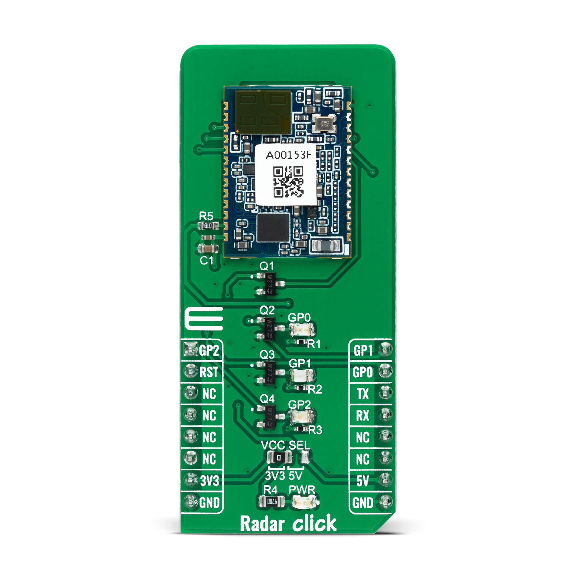
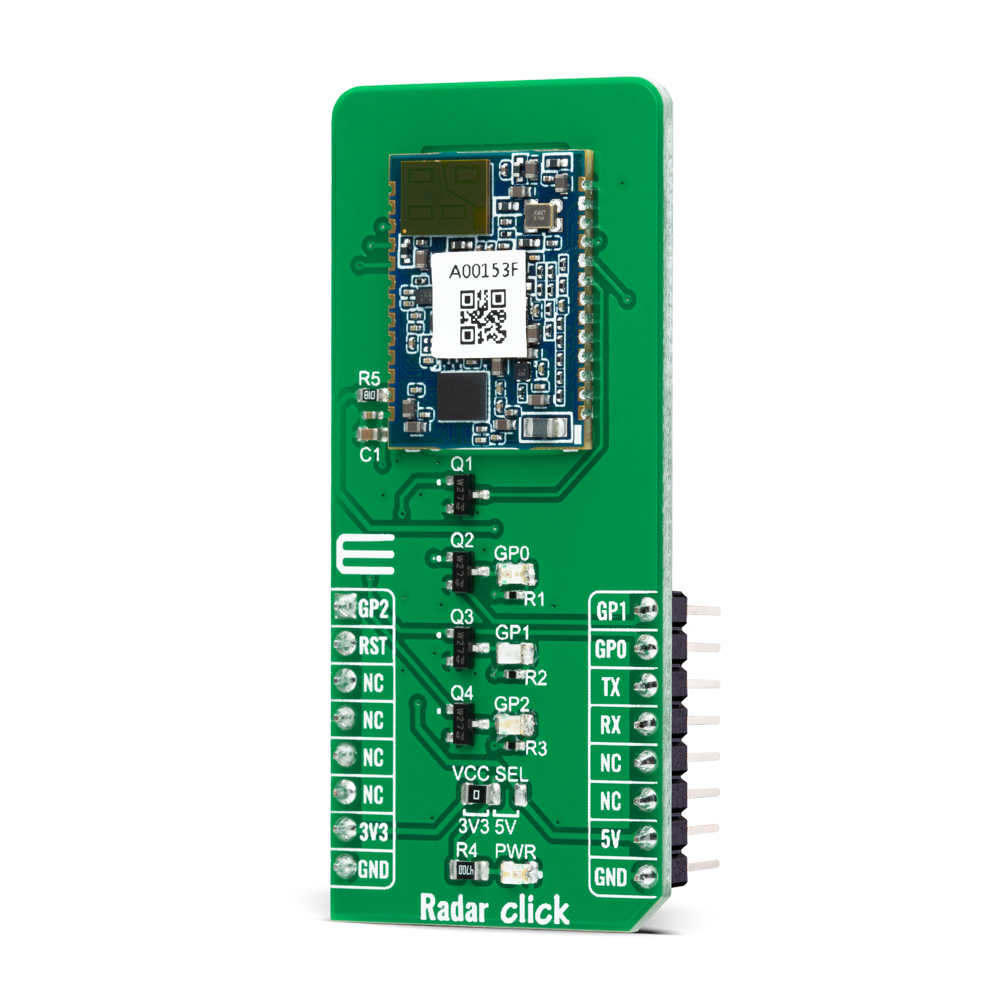
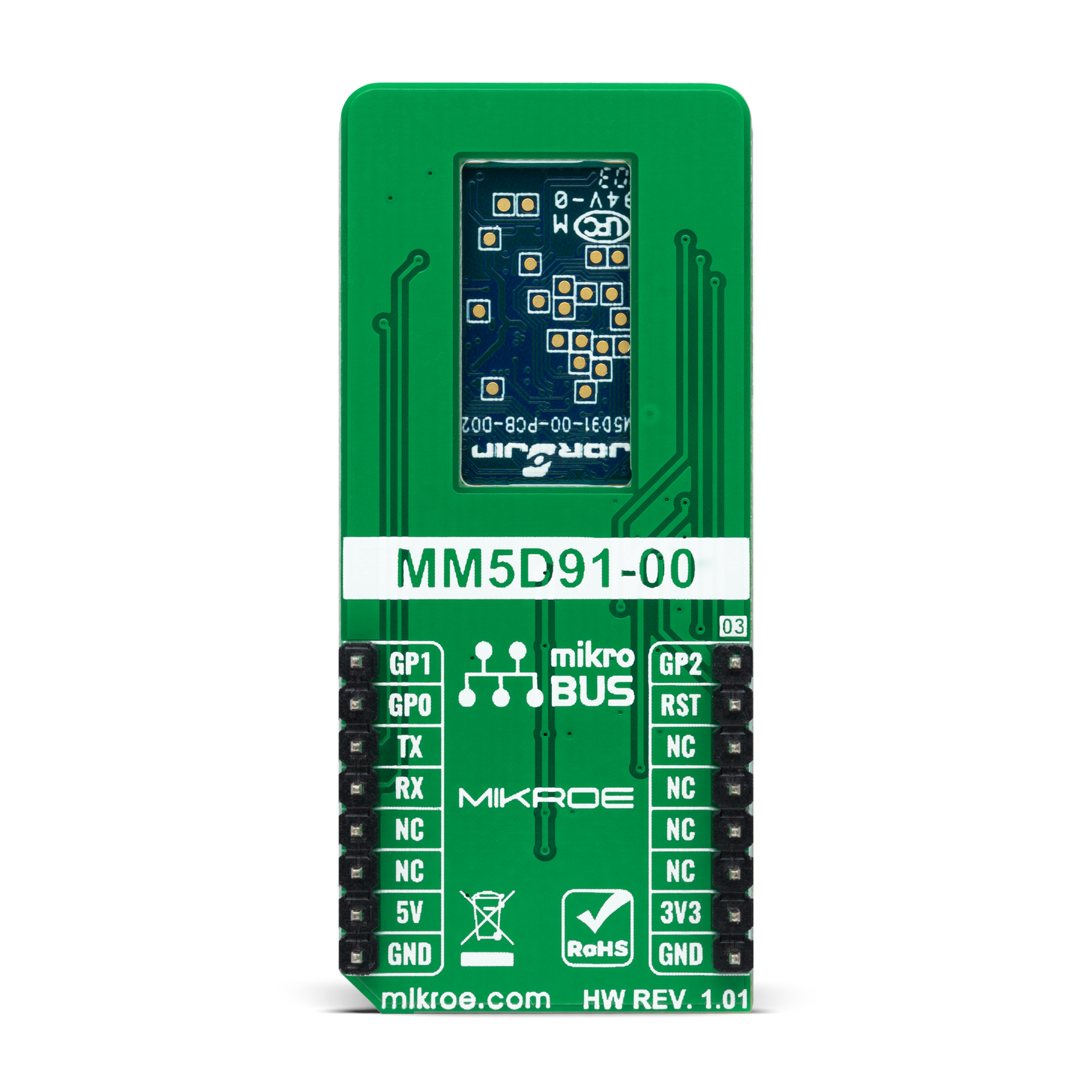
Radar Click is based on the MM5D91-00, a presence detection sensor module with integrated mmWave technology from Jorjin Technologies Inc. It counts the number of people entering or exiting an entrance, simplifies the implementation of mmWave sensors in the band of 61.0 to 61.5GHz, and includes the ARM Cortex-M4F-based processor system 1Tx 3Rx antenna and onboard regulator. This Click board™ is built to demonstrate the function of the entrance counter of the 60GHz radar sensor with its sophisticated radar presence detection algorithms. Characterized by low power consumption and high resolution, this board represents a suitable solution for various presence-sensing applications, from office and home to commercial buildings. Its detection range goes up
to 10m for macro motion, representing human movements, and 5m for micromotion, which stands for stationary human (normal breathing and blinking eyes) in sitting or standing positions with no active signs for at least 30 seconds. Immune to environmental factors such as temperature, wind, sunlight, and dust/debris, the MM5D91-00 also comes with azimuth and elevation field of view of ±45° and ±40°. The MM5D91-00 communicates with MCU using the UART interface with the default baud rate of 115200bps for data transfer. In addition, it also uses several mikroBUS™ pins. An active-low reset signal routed on the RST pin of the mikroBUS™ socket activates a hardware reset of the radar module. It also has three general-purpose pins, routed to the AN, PWM,
and INT pins of the mikroBUS™ socket marked as GP2, GP1, and GP0 to signal an essential change in device status, alongside its green, red, and blue LED indicators. Green LED stands for active presence indication, while red LED represents non-presence indication. Blue LED serves for bootloader mode indication. This Click board™ can operate with both 3.3V and 5V logic voltage levels selected via the VCC SEL jumper. This way, it is allowed for both 3.3V and 5V capable MCUs to use the communication lines properly. However, the Click board™ comes equipped with a library containing easy-to-use functions and an example code that can be used, as a reference, for further development.
Features overview
Development board
PIC18F57Q43 Curiosity Nano evaluation kit is a cutting-edge hardware platform designed to evaluate microcontrollers within the PIC18-Q43 family. Central to its design is the inclusion of the powerful PIC18F57Q43 microcontroller (MCU), offering advanced functionalities and robust performance. Key features of this evaluation kit include a yellow user LED and a responsive
mechanical user switch, providing seamless interaction and testing. The provision for a 32.768kHz crystal footprint ensures precision timing capabilities. With an onboard debugger boasting a green power and status LED, programming and debugging become intuitive and efficient. Further enhancing its utility is the Virtual serial port (CDC) and a debug GPIO channel (DGI
GPIO), offering extensive connectivity options. Powered via USB, this kit boasts an adjustable target voltage feature facilitated by the MIC5353 LDO regulator, ensuring stable operation with an output voltage ranging from 1.8V to 5.1V, with a maximum output current of 500mA, subject to ambient temperature and voltage constraints.

Microcontroller Overview
MCU Card / MCU

Architecture
PIC
MCU Memory (KB)
128
Silicon Vendor
Microchip
Pin count
48
RAM (Bytes)
8196
You complete me!
Accessories
Curiosity Nano Base for Click boards is a versatile hardware extension platform created to streamline the integration between Curiosity Nano kits and extension boards, tailored explicitly for the mikroBUS™-standardized Click boards and Xplained Pro extension boards. This innovative base board (shield) offers seamless connectivity and expansion possibilities, simplifying experimentation and development. Key features include USB power compatibility from the Curiosity Nano kit, alongside an alternative external power input option for enhanced flexibility. The onboard Li-Ion/LiPo charger and management circuit ensure smooth operation for battery-powered applications, simplifying usage and management. Moreover, the base incorporates a fixed 3.3V PSU dedicated to target and mikroBUS™ power rails, alongside a fixed 5.0V boost converter catering to 5V power rails of mikroBUS™ sockets, providing stable power delivery for various connected devices.

Used MCU Pins
mikroBUS™ mapper
Take a closer look
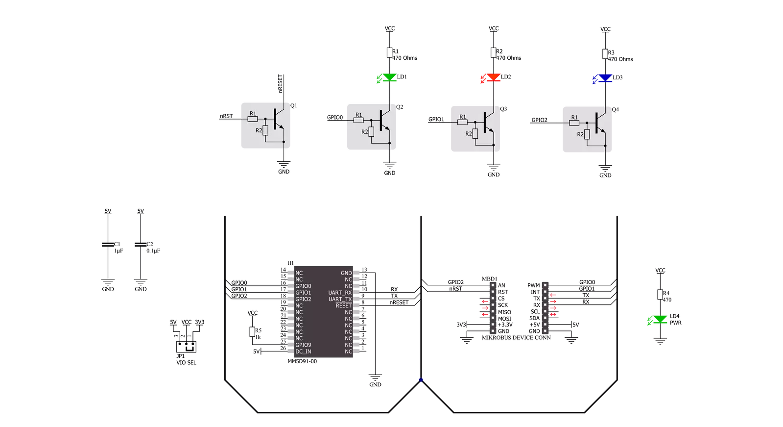
Click board™ Schematic
Step by step
Project assembly

Start by selecting your development board and Click board™. Begin with the Curiosity Nano with PIC18F57Q43 as your development board.


Track your results in real time
Application Output
1. Application Output - In Debug mode, the 'Application Output' window enables real-time data monitoring, offering direct insight into execution results. Ensure proper data display by configuring the environment correctly using the provided tutorial.

2. UART Terminal - Use the UART Terminal to monitor data transmission via a USB to UART converter, allowing direct communication between the Click board™ and your development system. Configure the baud rate and other serial settings according to your project's requirements to ensure proper functionality. For step-by-step setup instructions, refer to the provided tutorial.

3. Plot Output - The Plot feature offers a powerful way to visualize real-time sensor data, enabling trend analysis, debugging, and comparison of multiple data points. To set it up correctly, follow the provided tutorial, which includes a step-by-step example of using the Plot feature to display Click board™ readings. To use the Plot feature in your code, use the function: plot(*insert_graph_name*, variable_name);. This is a general format, and it is up to the user to replace 'insert_graph_name' with the actual graph name and 'variable_name' with the parameter to be displayed.

Software Support
Library Description
This library contains API for Radar Click driver.
Key functions:
radar_get_eventThis function waits for an IN/OUT event or ACK command response.radar_get_temperatureThis function reads the chip internal temperature.radar_set_detection_rangeThis function sets the min and max presence detection values.
Open Source
Code example
The complete application code and a ready-to-use project are available through the NECTO Studio Package Manager for direct installation in the NECTO Studio. The application code can also be found on the MIKROE GitHub account.
/*!
 * @file main.c
 * @brief Radar Click Example.
 *
 * # Description
 * This example demonstrates the use of Radar Click board by reading and parsing
 * events as well as the module internal temperature.
 *
 * The demo application is composed of two sections :
 *
 * ## Application Init
 * Initializes the driver and logger and performs the Click default configuration.
 *
 * ## Application Task
 * Waits for the detection event and then displays on the USB UART the distance of detected
 * object, accuracy, elapsed time since last reset, and the module internal temperature.
 *
 * @author Stefan Filipovic
 *
 */

#include "board.h"
#include "log.h"
#include "radar.h"

static radar_t radar;
static log_t logger;

void application_init ( void )
{
    log_cfg_t log_cfg;  /**< Logger config object. */
    radar_cfg_t radar_cfg;  /**< Click config object. */

    /**
     * Logger initialization.
     * Default baud rate: 115200
     * Default log level: LOG_LEVEL_DEBUG
     * @note If USB_UART_RX and USB_UART_TX
     * are defined as HAL_PIN_NC, you will
     * need to define them manually for log to work.
     * See @b LOG_MAP_USB_UART macro definition for detailed explanation.
     */
    LOG_MAP_USB_UART( log_cfg );
    log_init( &logger, &log_cfg );
    log_info( &logger, " Application Init " );

    // Click initialization.
    radar_cfg_setup( &radar_cfg );
    RADAR_MAP_MIKROBUS( radar_cfg, MIKROBUS_1 );
    if ( UART_ERROR == radar_init( &radar, &radar_cfg ) )
    {
        log_error( &logger, " Communication init." );
        for ( ; ; );
    }

    if ( RADAR_ERROR == radar_default_cfg ( &radar ) )
    {
        log_error( &logger, " Default configuration." );
        for ( ; ; );
    }

    log_info( &logger, " Application Task " );
}

void application_task ( void )
{
    uint8_t evt_id, evt_payload_size, evt_payload[ 16 ];
    if ( RADAR_OK == radar_get_event ( &radar, &evt_id, evt_payload, &evt_payload_size ) )
    {
        if ( RADAR_CMD_ID_DETECT_IN_EVT == evt_id )
        {
            log_printf( &logger, " EVENT: IN\r\n" );
            radar_float_bytes_t distance;
            memcpy ( distance.b_data, &evt_payload[ 8 ], 4 );
            radar_float_ieee_to_mchip ( &distance.f_data );
            log_printf( &logger, " Target distance: %.3f m\r\n", distance.f_data );
            memcpy ( distance.b_data, &evt_payload[ 12 ], 4 );
            radar_float_ieee_to_mchip ( &distance.f_data );
            log_printf( &logger, " Accuracy (+/-): %.3f m\r\n", distance.f_data );
        }
        else
        {
            log_printf( &logger, " EVENT: OUT\r\n" );
        }
        uint32_t evt_time = ( ( uint32_t ) evt_payload[ 3 ] << 24 ) | ( ( uint32_t ) evt_payload[ 2 ] << 16 ) |
                            ( ( uint16_t ) evt_payload[ 1 ] << 8 ) | evt_payload[ 0 ];
        log_printf( &logger, " Elapsed time: %.2f s\r\n", evt_time / 1000.0 );
        float temperature;
        if ( RADAR_OK == radar_get_temperature ( &radar, &temperature ) )
        {
            log_printf( &logger, " Temperature: %.2f C\r\n\n", temperature );
        }
    }
}

int main ( void )
{
    /* Do not remove this line or clock might not be set correctly. */
    #ifdef PREINIT_SUPPORTED
    preinit();
    #endif

    application_init( );

    for ( ; ; )
    {
        application_task( );
    }

    return 0;
}

// ------------------------------------------------------------------------ END


