Always be on time with AB0815 and PIC18F57Q43
RTC: Your silent reminder in a noisy world

Published Feb 13, 2024
Click board™
RTC 11 Click
Dev. board
Curiosity Nano with PIC18F57Q43
Compiler
NECTO Studio
MCU
PIC18F57Q43
Integrate reliable real-time clock into your solution to enable precise event sequencing and accurate time measurement
A
A
Hardware Overview
How does it work?
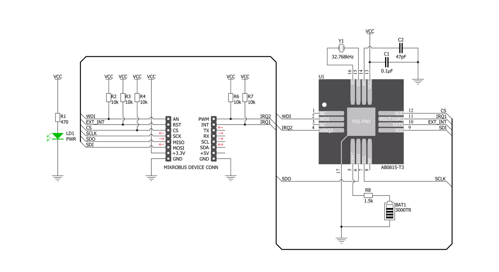
RTC 11 Click is based on the AB0815, an ultra-low-power coupled with a highly sophisticated feature set, the real-time clock from Abracon. The AB0815 is a full-function RTC and includes three feature groups: baseline and advanced timekeeping features and power management. Functions from each feature group may be controlled via I/O offset mapped registers accessed through the SPI serial interface. The baseline timekeeping feature group supports the standard 32.786 kHz crystal oscillation mode for maximum frequency accuracy with an ultra-low current draw of 22nA. This feature includes standard counters for minutes, hours, dates, months, years, and weekdays. A complement of countdown timers and alarms may additionally be set to initiate interrupts or
resets on several outputs. The most common configuration on this Click board™ is a battery-backed-up RTC, which maintains time and may hold data in RAM. In addition to the AB0815, the RTC 11 Click is equipped with a button cell battery holder compatible with the 3000TR battery holder, suitable for 12mm Coin Cell batteries. By utilizing an automatic backup switch, the AB0815 can use an external battery power source when there is no power supply on its main power terminals, thus allowing for uninterrupted operation. The AB0815 communicates with MCU using the standard SPI serial interface that supports modes 0 and 3 with a maximum frequency of 2 MHz. The flexible inputs of the AB0815 can be used to aggregate various interrupt sources, including external digital inputs,
analog levels, timers, and alarms, into a single interrupt source to an MCU. Based on this, functions like external interrupt or watchdog timer reset could be found on this Click board™ routed on the RST and AN pins of the mikroBUS™ socket labeled as EXI and WDI, as well as the primary and secondary interrupt outputs routed on the INT and PWM pins of the mikroBUS™ socket labeled as IT1 and IT2. This Click board™ can be operated only with a 3.3V logic voltage level. The board must perform appropriate logic voltage level conversion before using MCUs with different logic levels. Also, it comes equipped with a library containing functions and an example code that can be used as a reference for further development.


Features overview
Development board
PIC18F57Q43 Curiosity Nano evaluation kit is a cutting-edge hardware platform designed to evaluate microcontrollers within the PIC18-Q43 family. Central to its design is the inclusion of the powerful PIC18F57Q43 microcontroller (MCU), offering advanced functionalities and robust performance. Key features of this evaluation kit include a yellow user LED and a responsive
mechanical user switch, providing seamless interaction and testing. The provision for a 32.768kHz crystal footprint ensures precision timing capabilities. With an onboard debugger boasting a green power and status LED, programming and debugging become intuitive and efficient. Further enhancing its utility is the Virtual serial port (CDC) and a debug GPIO channel (DGI
GPIO), offering extensive connectivity options. Powered via USB, this kit boasts an adjustable target voltage feature facilitated by the MIC5353 LDO regulator, ensuring stable operation with an output voltage ranging from 1.8V to 5.1V, with a maximum output current of 500mA, subject to ambient temperature and voltage constraints.

Microcontroller Overview
MCU Card / MCU

Architecture
PIC
MCU Memory (KB)
128
Silicon Vendor
Microchip
Pin count
48
RAM (Bytes)
8196
You complete me!
Accessories
Curiosity Nano Base for Click boards is a versatile hardware extension platform created to streamline the integration between Curiosity Nano kits and extension boards, tailored explicitly for the mikroBUS™-standardized Click boards and Xplained Pro extension boards. This innovative base board (shield) offers seamless connectivity and expansion possibilities, simplifying experimentation and development. Key features include USB power compatibility from the Curiosity Nano kit, alongside an alternative external power input option for enhanced flexibility. The onboard Li-Ion/LiPo charger and management circuit ensure smooth operation for battery-powered applications, simplifying usage and management. Moreover, the base incorporates a fixed 3.3V PSU dedicated to target and mikroBUS™ power rails, alongside a fixed 5.0V boost converter catering to 5V power rails of mikroBUS™ sockets, providing stable power delivery for various connected devices.

Used MCU Pins
mikroBUS™ mapper
Take a closer look
Click board™ Schematic
Step by step
Project assembly

Start by selecting your development board and Click board™. Begin with the Curiosity Nano with PIC18F57Q43 as your development board.


Software Support
Library Description
This library contains API for RTC 11 Click driver.
Key functions:
rtc11_set_time- Set time hours, minutes and seconds functionrtc11_get_time- Get time hours, minutes and seconds functionrtc11_set_date- Set date day of the week, day, month and year function
Open Source
Code example
The complete application code and a ready-to-use project are available through the NECTO Studio Package Manager for direct installation in the NECTO Studio. The application code can also be found on the MIKROE GitHub account.
/*!
 * @file main.c
 * @brief RTC11 Click example
 *
 * # Description
 * This is an example that demonstrates the use of the RTC 11 Click board™.
 *
 * The demo application is composed of two sections :
 *
 * ## Application Init
 * Initalizes SPI, performs software reset, sets
 * system time and date, and starts clocking system.
 *
 * ## Application Task
 * Demonstrates use of RTC 11 Click board by reading and
 * displaying time and date via USART terminal.
 *
 * Additional Functions :
 *
 * void disp_day_of_the_week ( uint8_t w_day ) - Writes the day of the week on
 * USART terminal.
 *
 * @author Stefan Ilic
 *
 */

#include "board.h"
#include "log.h"
#include "rtc11.h"

static rtc11_t rtc11;
static log_t logger;

static rtc11_time_t time;
static rtc11_date_t date;

uint8_t sec_flag = 0xFF;

void disp_day_of_the_week ( uint8_t w_day ) {
    switch ( w_day )
    {
        case 0 :
        {
            log_printf( &logger, "Monday" );
            break;
        }
        case 1 :
        {
            log_printf( &logger, "Tuesday" );
            break;
        }
        case 2 :
        {
            log_printf( &logger, "Wednesday" );
            break;
        }
        case 3 :
        {
            log_printf( &logger, "Thursday" );
            break;
        }
        case 4 :
        {
            log_printf( &logger, "Friday" );
            break;
        }
        case 5 :
        {
            log_printf( &logger, "Saturday" );
            break;
        }
        case 6 :
        {
            log_printf( &logger, "Sunday" );
            break;
        }
        default :
        {
        break;
        }
    }
}
void application_init ( void ) {
    log_cfg_t log_cfg;  /**< Logger config object. */
    rtc11_cfg_t rtc11_cfg;  /**< Click config object. */

    /**
     * Logger initialization.
     * Default baud rate: 115200
     * Default log level: LOG_LEVEL_DEBUG
     * @note If USB_UART_RX and USB_UART_TX
     * are defined as HAL_PIN_NC, you will
     * need to define them manually for log to work.
     * See @b LOG_MAP_USB_UART macro definition for detailed explanation.
     */
    LOG_MAP_USB_UART( log_cfg );
    log_init( &logger, &log_cfg );
    log_info( &logger, " Application Init " );

    // Click initialization.

    rtc11_cfg_setup( &rtc11_cfg );
    RTC11_MAP_MIKROBUS( rtc11_cfg, MIKROBUS_1 );
    err_t init_flag  = rtc11_init( &rtc11, &rtc11_cfg );
    if ( SPI_MASTER_ERROR == init_flag ) {
        log_error( &logger, " Application Init Error. " );
        log_info( &logger, " Please, run program again... " );

        for ( ; ; );
    }
    log_printf( &logger,"------------------------\r\n" );
    log_printf( &logger," Software reset \r\n" );
    rtc11_soft_rst( &rtc11 );
    Delay_ms ( 100 );

    time.hours = 23;
    time.min = 59;
    time.sec = 55;
    log_printf( &logger,"------------------------\r\n" );
    log_printf( &logger," Setting time: %.2d:%.2d:%.2d \r\n", ( uint16_t ) time.hours, ( uint16_t ) time.min, ( uint16_t ) time.sec );
    rtc11_set_time ( &rtc11, time );
    Delay_ms ( 100 );

    date.day_of_week = 0;
    date.day = 19;
    date.month = 7;
    date.year = 21;
    log_printf( &logger,"------------------------\r\n" );
    log_printf( &logger," Setting date: %.2d/%.2d/%.2d \r\n", ( uint16_t ) date.day, ( uint16_t ) date.month, ( uint16_t ) date.year );
    rtc11_set_date( &rtc11, date );
    Delay_ms ( 100 );

    rtc11_stp_sys_slk ( &rtc11, RTC11_PROP_DIS );
    log_info( &logger, " Application Task " );
    log_printf( &logger,"------------------------\r\n" );
}

void application_task ( void ) {
    rtc11_get_time ( &rtc11, &time );
    Delay_ms ( 10 );
    rtc11_get_date ( &rtc11, &date );
    Delay_ms ( 10 );

    if ( sec_flag != time.sec ) {
        log_printf( &logger, " Date: " );
        disp_day_of_the_week( date.day_of_week );
        log_printf( &logger, " %.2d/%.2d/20%.2d \r\n", ( uint16_t ) date.day, ( uint16_t ) date.month, ( uint16_t ) date.year );
        log_printf( &logger, " Time: %.2d:%.2d:%.2d \r\n", ( uint16_t ) time.hours, ( uint16_t ) time.min, ( uint16_t ) time.sec );
        log_printf( &logger,"--------------------------\r\n" );
    }
    sec_flag = time.sec;
}

int main ( void )
{
    /* Do not remove this line or clock might not be set correctly. */
    #ifdef PREINIT_SUPPORTED
    preinit();
    #endif

    application_init( );

    for ( ; ; )
    {
        application_task( );
    }

    return 0;
}

// ------------------------------------------------------------------------ END
Additional Support
Resources
Category:RTC


