Achieve unmatched accuracy and reliability in temperature monitoring with LTC2986 and PIC18F57Q43
ThermoGuard: Your temperature sentinel

Published Feb 13, 2024
Click board™
Temp Probe Click
Dev Board
Curiosity Nano with PIC18F57Q43
Compiler
NECTO Studio
MCU
PIC18F57Q43
Keep your processes running smoothly with our thermocouple temperature monitoring system - where heat is always under control.
A
A
Hardware Overview
How does it work?
Temp Probe Click is based on the LTC2986, a high-accuracy thermocouple temperature monitoring system with 0.1°C accuracy and 0.001°C resolution from Analog Devices. The LTC2986 simultaneously measures the thermocouple output and the cold junction temperature and performs all required calculations to report the thermocouple temperature in °C or °F. It combines high accuracy with a simple operation composed of five states: Start-Up, Channel Assignment, Initiate Conversion, Conversion, and Read Results. It works with ground-referenced sensors without amplifiers, negative supplies, or level shift circuitry where signals are simultaneously digitized with three high accuracy, 24-bit Δ-Σ ADCs using an internal 15ppm/°C reference. Thermocouples can measure temperatures from –265°C to more than 1.800°C, generating a voltage as a function of the temperature difference between the tip
(thermocouple temperature) and the electrical connection on the circuit board (cold junction temperature). To determine the thermocouple temperature, an accurate measurement of the cold junction temperature is required, known as cold junction compensation. The LTC2986 performs automatic thermocouple cold junction compensation using any external sensor. The onboard PCC-SMP connector is a perfect solution for bringing thermocouple probes to the PCB, suitable for all K-type probes. To use Temp Probe Click, the user needs to connect the appropriate K-type thermocouple probe, which is not included in the package, into the PCC-SMP connector. Type-K thermocouple with glass braid insulation, available in our store, is used for precision measurements of high temperatures allowing this Click board™ to measure temperature up to 480°C (900°F). Temp Probe Click communicates with MCU using the
SPI serial interface with a maximum SPI frequency of 2 MHz. The LTC2986 utilizes the interrupt pin routed on the INT pin of the mikroBUS™ socket to signal when the device is busy, either during Start-Up or while a conversion cycle is in progress. Alongside this feature, this Click board™ also has a Reset function routed on the RST pin of the mikroBUS™ socket that will put the LTC2986 into the reset state by driving the RST pin LOW. Once this pin is returned HIGH, the device initiates its Start-Up sequence. This Click board™ can operate with either 3.3V or 5V logic voltage levels selected via the VCC SEL jumper. This way, both 3.3V and 5V capable MCUs can use the communication lines properly. Also, this Click board™ comes equipped with a library containing easy-to-use functions and an example code that can be used as a reference for further development.

Features overview
Development board
PIC18F57Q43 Curiosity Nano evaluation kit is a cutting-edge hardware platform designed to evaluate microcontrollers within the PIC18-Q43 family. Central to its design is the inclusion of the powerful PIC18F57Q43 microcontroller (MCU), offering advanced functionalities and robust performance. Key features of this evaluation kit include a yellow user LED and a responsive
mechanical user switch, providing seamless interaction and testing. The provision for a 32.768kHz crystal footprint ensures precision timing capabilities. With an onboard debugger boasting a green power and status LED, programming and debugging become intuitive and efficient. Further enhancing its utility is the Virtual serial port (CDC) and a debug GPIO channel (DGI
GPIO), offering extensive connectivity options. Powered via USB, this kit boasts an adjustable target voltage feature facilitated by the MIC5353 LDO regulator, ensuring stable operation with an output voltage ranging from 1.8V to 5.1V, with a maximum output current of 500mA, subject to ambient temperature and voltage constraints.

Microcontroller Overview
MCU Card / MCU

Architecture
PIC
MCU Memory (KB)
128
Silicon Vendor
Microchip
Pin count
48
RAM (Bytes)
8196
You complete me!
Accessories
Curiosity Nano Base for Click boards is a versatile hardware extension platform created to streamline the integration between Curiosity Nano kits and extension boards, tailored explicitly for the mikroBUS™-standardized Click boards and Xplained Pro extension boards. This innovative base board (shield) offers seamless connectivity and expansion possibilities, simplifying experimentation and development. Key features include USB power compatibility from the Curiosity Nano kit, alongside an alternative external power input option for enhanced flexibility. The onboard Li-Ion/LiPo charger and management circuit ensure smooth operation for battery-powered applications, simplifying usage and management. Moreover, the base incorporates a fixed 3.3V PSU dedicated to target and mikroBUS™ power rails, alongside a fixed 5.0V boost converter catering to 5V power rails of mikroBUS™ sockets, providing stable power delivery for various connected devices.

The Type-K thermocouple, equipped with glass braid insulation, is a versatile tool designed for precision temperature measurements, particularly in high-temperature environments. With a calibrated Type-K configuration and a 24 AWG gage wire spanning 2 meters, this probe is engineered to provide reliable readings. Its operational temperature range extends to 480°C (900°F), making it suitable for demanding applications. The glass braid insulation ensures durability and stability during measurements, and the connector body can withstand temperatures up to 220°C (425°F). The Type-K thermocouple probe features a PCC-SMP connector at its end, which offers compatibility with THERMO Click and Thermo K Click boards. This connectivity makes it a valuable tool for various industrial and scientific settings, where precision and reliability in temperature monitoring are essential.

Used MCU Pins
mikroBUS™ mapper
Take a closer look
Schematic

Step by step
Project assembly

Start by selecting your development board and Click board™. Begin with the Curiosity Nano with PIC18F57Q43 as your development board.


Track your results in real time
Application Output via Debug Mode
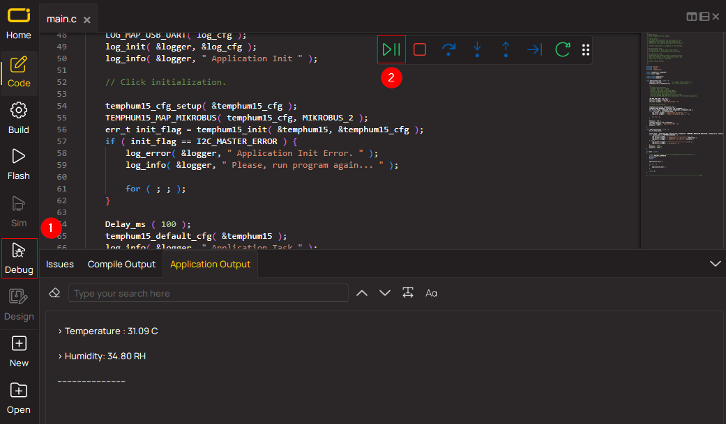
1. Once the code example is loaded, pressing the "DEBUG" button initiates the build process, programs it on the created setup, and enters Debug mode.
2. After the programming is completed, a header with buttons for various actions within the IDE becomes visible. Clicking the green "PLAY" button starts reading the results achieved with the Click board™. The achieved results are displayed in the Application Output tab.
Software Support
Library Description
This library contains API for Temp Probe Click driver.
Key functions:
tempprobe_write_word- Word Write function.tempprobe_read_bytes- Byte Read function.tempprobe_read_temp- Temperature Read function.
Open Source
Code example
This example can be found in NECTO Studio. Feel free to download the code, or you can copy the code below.
/*!
 * @file main.c
 * @brief TempProbe Click example
 *
 * # Description
 * This is an example that demonstrates the use of the Temp Probe Click board.
 *
 * The demo application is composed of two sections :
 *
 * ## Application Init
 * Initializes SPI interface, setting temperature format to celsius and performs a device
 * configuration for proper functioning and configures the desired channels.
 *
 * ## Application Task
 * Measure temperatures from all sensors and display the measurements on the serial port.
 *
 * @author Stefan Ilic
 *
 */

#include "board.h"
#include "log.h"
#include "tempprobe.h"

static tempprobe_t tempprobe;
static log_t logger;

void application_init ( void )
{
    log_cfg_t log_cfg;  /**< Logger config object. */
    tempprobe_cfg_t tempprobe_cfg;  /**< Click config object. */

    /**
     * Logger initialization.
     * Default baud rate: 115200
     * Default log level: LOG_LEVEL_DEBUG
     * @note If USB_UART_RX and USB_UART_TX
     * are defined as HAL_PIN_NC, you will
     * need to define them manually for log to work.
     * See @b LOG_MAP_USB_UART macro definition for detailed explanation.
     */
    LOG_MAP_USB_UART( log_cfg );
    log_init( &logger, &log_cfg );
    log_info( &logger, " Application Init " );

    // Click initialization.
    tempprobe_cfg_setup( &tempprobe_cfg );
    TEMPPROBE_MAP_MIKROBUS( tempprobe_cfg, MIKROBUS_1 );
    if ( SPI_MASTER_ERROR == tempprobe_init( &tempprobe, &tempprobe_cfg ) )
    {
        log_error( &logger, " Application Init Error. " );
        log_info( &logger, " Please, run program again... " );
        for ( ; ; );
    }
    tempprobe_reset( &tempprobe );
    Delay_ms ( 300 );
    if ( TEMPPROBE_ERROR == tempprobe_default_cfg( &tempprobe ) )
    {
        log_error( &logger, " Config Error " );
        for ( ; ; );
    }
    Delay_ms ( 300 );

    log_info( &logger, " Application Task " );
}

void application_task ( void )
{
    float temperature_k = 0;
    float temperature_pn = 0;
    tempprobe_write_byte( &tempprobe, TEMPPROBE_REG_COMM_STATUS, TEMPPROBE_START_CONV );
    while ( TEMPPROBE_NO_BUSY_STATE != tempprobe_check_busy( &tempprobe ) );

    tempprobe_read_temp( &tempprobe, TEMPPROBE_REG_PN_JUNCTION_CONV_RES, &temperature_pn );
    log_printf( &logger, " PN-Junction: %.2f C\r\n", temperature_pn );
    tempprobe_read_temp( &tempprobe, TEMPPROBE_REG_THERMO_K_CONV_RES, &temperature_k );
    log_printf( &logger, " Thermo K:    %.2f C\r\n", temperature_k );

    log_printf( &logger, "------------------------\r\n" );
    Delay_ms ( 1000 );
    Delay_ms ( 500 );
}

int main ( void )
{
    /* Do not remove this line or clock might not be set correctly. */
    #ifdef PREINIT_SUPPORTED
    preinit();
    #endif

    application_init( );

    for ( ; ; )
    {
        application_task( );
    }

    return 0;
}

// ------------------------------------------------------------------------ END


