Unlock the power of linear Hall switching using MLX90242 and PIC32MZ1024EFH064
Powerful sensing, unparalleled precision

Published Jun 20, 2023
Click board™
LIN HALL Click
Dev. board
PIC32MZ clicker
Compiler
NECTO Studio
MCU
PIC32MZ1024EFH064
Empower your design with Linear Hall Switch engineered to provide accurate and proportional output, perfect for applications demanding reliable linear position and current sensing
A
A
Hardware Overview
How does it work?
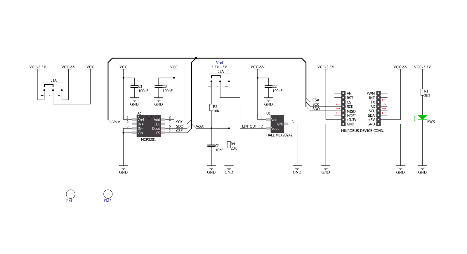
LIN HALL Click is based on the MLX90242, a linear Hall-effect sensor designed in CMOS technology from Melexis Technologies. The MLX90242 features active error correction circuitry (Hall plate quadrature spinning current and chopper-stabilized amplifier), virtually eliminating the offset errors usually associated with Hall-effect devices. It allows using generic magnets, making it suitable for highly accurate rotary and linear position detection in automotive and industrial applications. The ratiometric output voltage of the MLX90242 is proportional to the supply voltage.
For a positive slope, the voltage at the output will increase as a South magnetic field is applied to the branded face of the MLX90242. Conversely, the voltage output will decrease in the presence of a North magnetic field. For a negative slope, the voltage at the output will increase as a North magnetic field is applied to the branded face of the MLX90242. Conversely, the voltage output will decrease in the presence of a South magnetic field. The output signal of the MLX90242 is then converted to a digital value using MCP3201, a successive approximation A/D converter with a
12-bit resolution from Microchip using a 3-wire SPI compatible interface (read-only). This Click board™ can operate with both 3.3V and 5V logic voltage levels selected via the VOLTAGE LEVEL jumper. It should be highlighted that the MLX90242 works exclusively at 5V, where it is necessary to perform appropriate logic voltage level conversion before using MCUs with different logic levels. However, the Click board™ comes equipped with a library containing functions and an example code that can be used, as a reference, for further development.

Features overview
Development board
PIC32MZ Clicker is a compact starter development board that brings the flexibility of add-on Click boards™ to your favorite microcontroller, making it a perfect starter kit for implementing your ideas. It comes with an onboard 32-bit PIC32MZ microcontroller with FPU from Microchip, a USB connector, LED indicators, buttons, a mikroProg connector, and a header for interfacing with external electronics. Thanks to its compact design with clear and easy-recognizable silkscreen markings, it provides a fluid and immersive working experience, allowing access anywhere and under
any circumstances. Each part of the PIC32MZ Clicker development kit contains the components necessary for the most efficient operation of the same board. In addition to the possibility of choosing the PIC32MZ Clicker programming method, using USB HID mikroBootloader, or through an external mikroProg connector for PIC, dsPIC, or PIC32 programmer, the Clicker board also includes a clean and regulated power supply module for the development kit. The USB Micro-B connection can provide up to 500mA of current, which is more than enough to operate all onboard
and additional modules. All communication methods that mikroBUS™ itself supports are on this board, including the well-established mikroBUS™ socket, reset button, and several buttons and LED indicators. PIC32MZ Clicker is an integral part of the Mikroe ecosystem, allowing you to create a new application in minutes. Natively supported by Mikroe software tools, it covers many aspects of prototyping thanks to a considerable number of different Click boards™ (over a thousand boards), the number of which is growing every day.

Microcontroller Overview
MCU Card / MCU

Architecture
PIC32
MCU Memory (KB)
1024
Silicon Vendor
Microchip
Pin count
64
RAM (Bytes)
524288
Used MCU Pins
mikroBUS™ mapper
Take a closer look
Click board™ Schematic
Step by step
Project assembly

Start by selecting your development board and Click board™. Begin with the PIC32MZ clicker as your development board.


Software Support
Library Description
This library contains API for LIN HALL Click driver.
Key functions:
linhall_read_data- Read 12-bit data function
Open Source
Code example
The complete application code and a ready-to-use project are available through the NECTO Studio Package Manager for direct installation in the NECTO Studio. The application code can also be found on the MIKROE GitHub account.
/*!
 * \file
 * \brief LinHall Click example
 *
 * # Description
 * This is a example which demonstrates the use of Lin Hall Click board.
 *
 * The demo application is composed of two sections :
 *
 * ## Application Init
 * Initializes SPI and LOG structures, initialization driver enable's
 * - SPI and start write log.
 *
 * ## Application Task
 * Read 12-bit ADC value from the MCP3201 chip.
 * Results are being sent to the Usart Terminal where you can track their changes.
 * All data logs on usb uart for aproximetly every 100 ms when the ADC value changes.
 *
 * \author MikroE Team
 *
 */
// ------------------------------------------------------------------- INCLUDES

#include "board.h"
#include "log.h"
#include "linhall.h"

// ------------------------------------------------------------------ VARIABLES

static linhall_t linhall;
static log_t logger;

static uint16_t value_adc;
static uint16_t value_adc_old;
static uint16_t sensitivity;

// ------------------------------------------------------ APPLICATION FUNCTIONS

void application_init ( void )
{
    log_cfg_t log_cfg;
    linhall_cfg_t cfg;

    /**
     * Logger initialization.
     * Default baud rate: 115200
     * Default log level: LOG_LEVEL_DEBUG
     * @note If USB_UART_RX and USB_UART_TX
     * are defined as HAL_PIN_NC, you will
     * need to define them manually for log to work.
     * See @b LOG_MAP_USB_UART macro definition for detailed explanation.
     */
    LOG_MAP_USB_UART( log_cfg );
    log_init( &logger, &log_cfg );
    log_info( &logger, "---- Application Init ----" );

    //  Click initialization.

    linhall_cfg_setup( &cfg );
    LINHALL_MAP_MIKROBUS( cfg, MIKROBUS_1 );
    linhall_init( &linhall, &cfg );

    log_printf( &logger, "  Lin Hall Click  \r\n" );
    log_printf( &logger, "------------------\r\n" );
    Delay_ms ( 100 );

    value_adc_old = 0;
    sensitivity = 30;
}

void application_task ( void )
{
    value_adc = linhall_read_data( &linhall );

    if ( ( ( value_adc - value_adc_old ) > sensitivity ) && ( ( value_adc_old - value_adc ) > sensitivity ) )
    {
        log_printf( &logger, "  ADC Value : %d \r\n", value_adc );
        log_printf( &logger, "------------------\r\n" );

        value_adc_old = value_adc;
        Delay_ms ( 100 );
    }
}

int main ( void )
{
    /* Do not remove this line or clock might not be set correctly. */
    #ifdef PREINIT_SUPPORTED
    preinit();
    #endif

    application_init( );

    for ( ; ; )
    {
        application_task( );
    }

    return 0;
}


// ------------------------------------------------------------------------ END
Additional Support
Resources
Category:Magnetic


