Simplify navigation, commands, and access with ATtiny817 and PIC18F57Q43
Unlock your world with a gentle tap!

Published Feb 13, 2024
Click board™
TouchKey 2 Click
Dev. board
Curiosity Nano with PIC18F57Q43
Compiler
NECTO Studio
MCU
PIC18F57Q43
Our touchkey solution revolutionizes user interaction by providing a sensitive and elegant touch interface that responds effortlessly to the gentlest tap of your finger
A
A
Hardware Overview
How does it work?
TocuhKey 2 Click is based on the ATtiny817, an integrated touch QTouch® controller from Microchip. This Click is designed to run on a 3.3V power supply. The four LEDs onboard the click indicate when the Key (Pad) is pressed. TouchKey 2 click communicates with the target microcontroller over the UART interface. You can use TouchKey 2 Click in all conditions without fearing something will happen due to moisture and water droplets falling on it. The plastic overlay on the TouchKey 2 click protects the board from moisture. Thanks to this feature, the electronic components are safe. The ATtiny817 has a driven shield for improved moisture and noise-handling performance. Microchip's ATtiny817 is a
microcontroller that uses an 8-bit AVR® processor with hardware multiplier, running at up to 20MHz and with up to 8KB Flash, 512 bytes of SRAM, and 128 bytes of EEPROM. The ATtiny817 uses the latest technologies from Microchip with a flexible and low-power architecture, including Event System and SleepWalking, accurate analog features, and advanced peripherals. Capacitive touch interfaces with proximity sensing and a driven shield are supported with the integrated QTouch® peripheral touch controller. The module supports wake-up on touch from power-save sleep mode. Capacitive buttons can be toggled even when placed under a layer of glass or paper. There are four LEDs for four touch keys. If key A is pressed,
LED_A is ON, and such. In addition, there is UART communication between ATtiny817 and the main MCU. The header onboard the TouchKey 2 click can be used for device programming. Current firmware sends data packets via UART (based on the demo example in our library). SPI communication is possible with firmware modifications. This Click board™ can be operated only with a 3.3V logic voltage level. The board must perform appropriate logic voltage level conversion before using MCUs with different logic levels. Also, it comes equipped with a library containing functions and an example code that can be used, as a reference, for further development.


Features overview
Development board
PIC18F57Q43 Curiosity Nano evaluation kit is a cutting-edge hardware platform designed to evaluate microcontrollers within the PIC18-Q43 family. Central to its design is the inclusion of the powerful PIC18F57Q43 microcontroller (MCU), offering advanced functionalities and robust performance. Key features of this evaluation kit include a yellow user LED and a responsive
mechanical user switch, providing seamless interaction and testing. The provision for a 32.768kHz crystal footprint ensures precision timing capabilities. With an onboard debugger boasting a green power and status LED, programming and debugging become intuitive and efficient. Further enhancing its utility is the Virtual serial port (CDC) and a debug GPIO channel (DGI
GPIO), offering extensive connectivity options. Powered via USB, this kit boasts an adjustable target voltage feature facilitated by the MIC5353 LDO regulator, ensuring stable operation with an output voltage ranging from 1.8V to 5.1V, with a maximum output current of 500mA, subject to ambient temperature and voltage constraints.

Microcontroller Overview
MCU Card / MCU

Architecture
PIC
MCU Memory (KB)
128
Silicon Vendor
Microchip
Pin count
48
RAM (Bytes)
8196
You complete me!
Accessories
Curiosity Nano Base for Click boards is a versatile hardware extension platform created to streamline the integration between Curiosity Nano kits and extension boards, tailored explicitly for the mikroBUS™-standardized Click boards and Xplained Pro extension boards. This innovative base board (shield) offers seamless connectivity and expansion possibilities, simplifying experimentation and development. Key features include USB power compatibility from the Curiosity Nano kit, alongside an alternative external power input option for enhanced flexibility. The onboard Li-Ion/LiPo charger and management circuit ensure smooth operation for battery-powered applications, simplifying usage and management. Moreover, the base incorporates a fixed 3.3V PSU dedicated to target and mikroBUS™ power rails, alongside a fixed 5.0V boost converter catering to 5V power rails of mikroBUS™ sockets, providing stable power delivery for various connected devices.

Used MCU Pins
mikroBUS™ mapper
Take a closer look
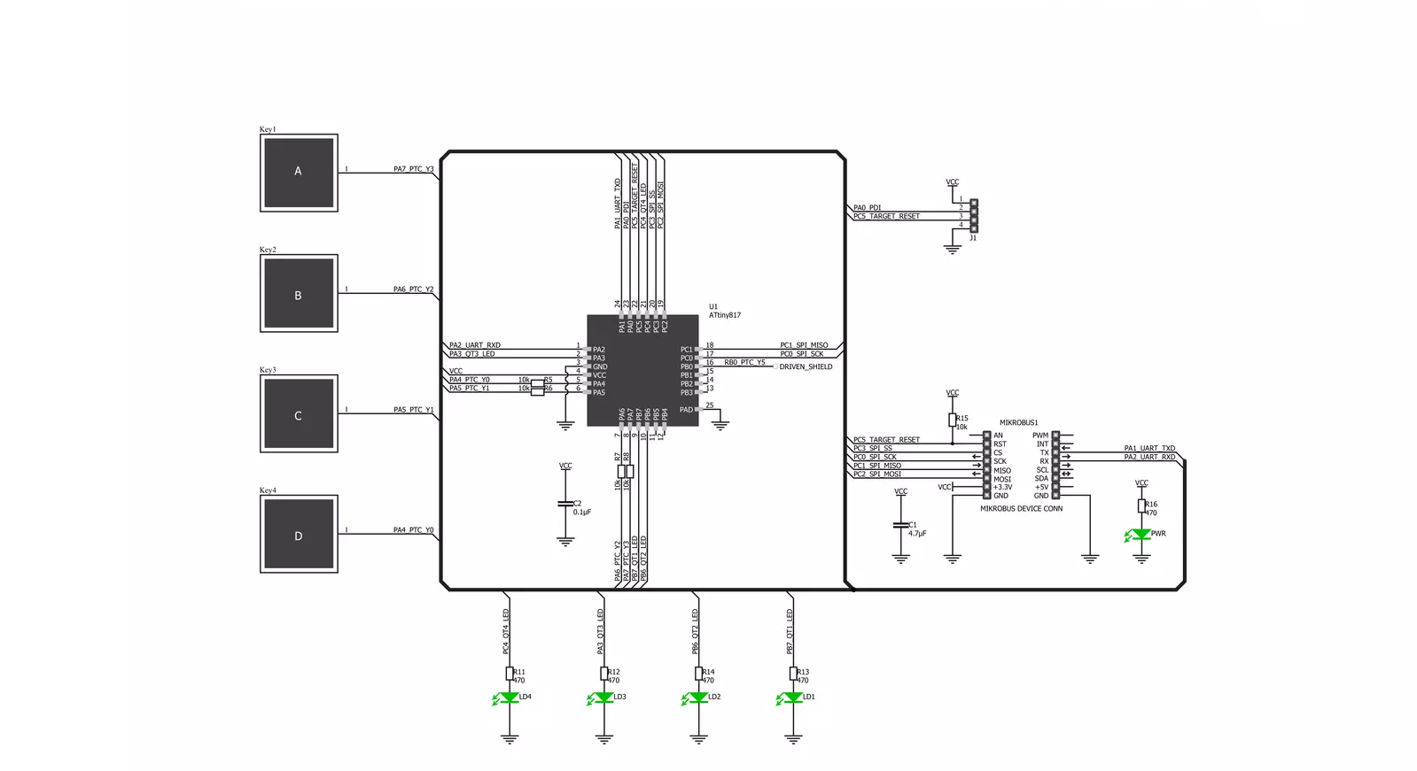
Click board™ Schematic
Step by step
Project assembly

Start by selecting your development board and Click board™. Begin with the Curiosity Nano with PIC18F57Q43 as your development board.


Software Support
Library Description
This library contains API for TouchKey 2 Click driver.
Key functions:
touchkey2_set_reset_pin- Set reset pin functiontouchkey2_clear_reset_pin- Clear reset pin functiontouchkey2_target_reset- Reset function
Open Source
Code example
The complete application code and a ready-to-use project are available through the NECTO Studio Package Manager for direct installation in the NECTO Studio. The application code can also be found on the MIKROE GitHub account.
/*!
 * \file
 * \brief Touchkey2 Click example
 *
 * # Description
 * This application is touch controller.
 *
 * The demo application is composed of two sections :
 *
 * ## Application Init
 * Initalizes device and makes an initial log.
 *
 * ## Application Task
 * Checks if new data byte have received in rx buffer (ready for reading),
   and if ready than reads one byte from rx buffer, that show if and what key is pressed.
 *
 * \author MikroE Team
 *
 */
// ------------------------------------------------------------------- INCLUDES

#include "board.h"
#include "log.h"
#include "touchkey2.h"

// ------------------------------------------------------------------ VARIABLES

static touchkey2_t touchkey2;
static log_t logger;

// ------------------------------------------------------ APPLICATION FUNCTIONS

void application_init ( void )
{
    log_cfg_t log_cfg;
    touchkey2_cfg_t cfg;

    /**
     * Logger initialization.
     * Default baud rate: 115200
     * Default log level: LOG_LEVEL_DEBUG
     * @note If USB_UART_RX and USB_UART_TX
     * are defined as HAL_PIN_NC, you will
     * need to define them manually for log to work.
     * See @b LOG_MAP_USB_UART macro definition for detailed explanation.
     */
    LOG_MAP_USB_UART( log_cfg );
    log_init( &logger, &log_cfg );
    log_info( &logger, "---- Application Init ----" );

    //  Click initialization.

    touchkey2_cfg_setup( &cfg );
    TOUCHKEY2_MAP_MIKROBUS( cfg, MIKROBUS_1 );
    touchkey2_init( &touchkey2, &cfg );
}

void application_task ( void )
{
    char tmp;

    tmp = touchkey2_generic_single_read( &touchkey2 );
    if( tmp == 0x00 )
    {
        log_printf( &logger, "   Key released\r\n" );
        log_printf( &logger, "------------------- \r\n" );
    }
    else if( tmp == 0x01 )
    {
        log_printf( &logger, "   Key A pressed\r\n" );
        log_printf( &logger, "------------------- \r\n" );
    }
    else if( tmp == 0x02 )
    {
        log_printf( &logger, "   Key B pressed\r\n" );
        log_printf( &logger, "------------------- \r\n" );
    }
    else if( tmp == 0x04 )
    {
        log_printf( &logger, "   Key C pressed\r\n" );
        log_printf( &logger, "------------------- \r\n" );
    }
    else if( tmp == 0x08 )
    {
        log_printf( &logger, "   Key D pressed \r\n" );
        log_printf( &logger, "------------------- \r\n" );
    }
}

int main ( void )
{
    /* Do not remove this line or clock might not be set correctly. */
    #ifdef PREINIT_SUPPORTED
    preinit();
    #endif

    application_init( );

    for ( ; ; )
    {
        application_task( );
    }

    return 0;
}


// ------------------------------------------------------------------------ END
Additional Support
Resources
Category:Capacitive


