Embrace the future of communication with BM832A and PIC18F47K42TQFP
Bluetooth 5.0 solution that has it all!

Published Feb 13, 2024
Click board™
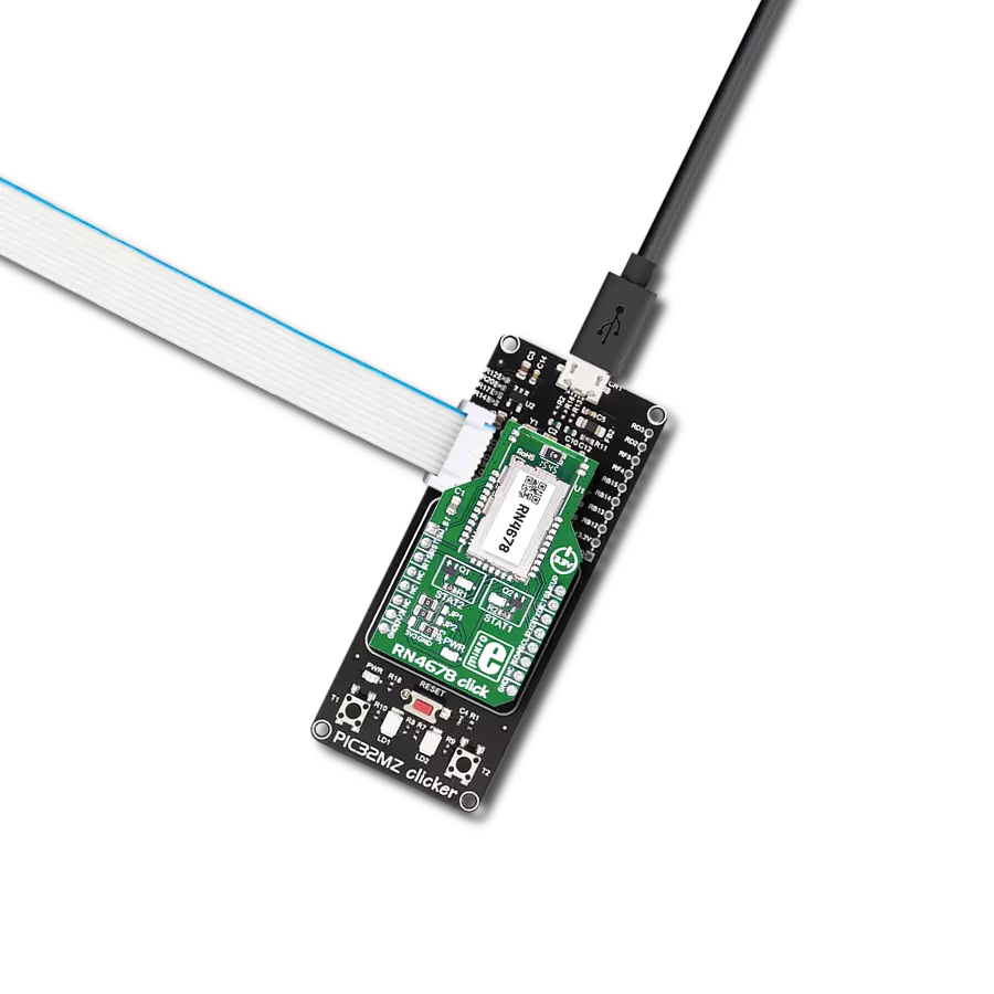
BLE 12 Click
Dev. board
Curiosity Nano with PIC18F47K42
Compiler
NECTO Studio
MCU
PIC18F47K42TQFP
Enjoy high-quality audio and data transfer without limitations
A
A
Hardware Overview
How does it work?
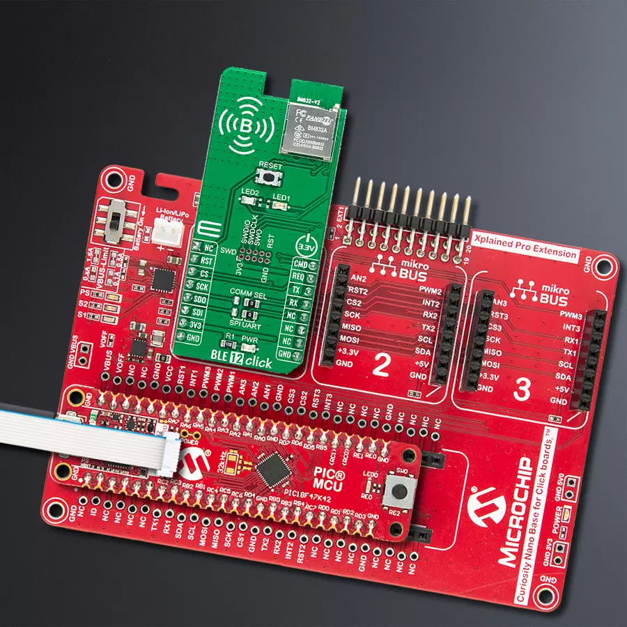
BLE 12 Click is based on the BM832A, a highly flexible, ultra-low power Bluetooth module that provides BLE connectivity for any embedded application from Fanstel. The BM832A module is based on the Nordic nRF52 SoC, which integrates a 64MHz, 32bit ARM Cortex M4 processor with a floating-point unit (FPU) and a 2.4GHz multiprotocol radio (supporting Bluetooth 5.0 and an integrated PCB trace antenna), featuring -96dBm RX sensitivity (depending on data rate), alongside 192kB Flash memory and 24kB RAM. BLE 12 Click allows UART and SPI interfaces, with commonly used UART RX and TX pins as its default communication protocol for exchanging AT commands operating at 115200 bps by default configuration, to transmit and exchange data with the host MCU. The selection can be made by positioning SMD jumpers labeled COMM SEL in an appropriate position. Note that all the jumpers' positions must be on the same side, or the Click
board™ may become unresponsive. The CMD pin routed on the PWM pin of the mikroBUS™ represents the communication-activation feature. A high logic state of the CMD pin allows the module to communicate with the MCU, while a low state allows data to be sent to a far-end device (for example, a smartphone) transparently. With the selected UART interface, power consumption can be reduced by sending the command "AT+STOP". The CS pin must be set to a low logic state for 200μs or more to wake up the UART interface. Besides, it has an additional data-ready signal, labeled as REQ and routed on the INT pin of the mikroBUS™ socket, indicating that new data is ready for the host. This Click board™ comes with worldwide regulatory certifications and offers enhanced performance, security, and reliability to support IoT products running on Bluetooth networks. Besides, at the center of the BLE 12 Click, an additional unpopulated header offers full
support for debugging and programming capabilities. With this header, the user can use a Serial Wire Debug interface for programming and debugging, available through the SWD interface pins (SWDIO, SWCLK, and SWO). In addition to the appropriate interfaces, this Click board™ also has some additional features. A Reset button routed to the RST pin on the mikroBUS™ socket puts the module into a Reset state, while the two additional LED indicators, yellow and red LEDs labeled as LED1 and LED2, can be used for optional user-configurable visual indication. This Click board™ can be operated only with a 3.3V logic voltage level. The board must perform appropriate logic voltage level conversion before using MCUs with different logic levels. Also, it comes equipped with a library containing functions and an example code that can be used, as a reference, for further development.

Features overview
Development board
PIC18F47K42 Curiosity Nano evaluation kit is a cutting-edge hardware platform designed to evaluate the PIC18F47K42 microcontroller (MCU). Central to its design is the inclusion of the powerful PIC18F47K42 microcontroller (MCU), offering advanced functionalities and robust performance. Key features of this evaluation kit include a yellow user LED and a responsive mechanical user switch
providing seamless interaction and testing. The provision for a 32.768kHz crystal footprint ensures precision timing capabilities. With an onboard debugger boasting a green power and status LED, programming and debugging become intuitive and efficient. Further enhancing its utility is the Virtual serial port (CDC) and a debug GPIO channel (DGI GPIO), offering extensive connectivity options.
Powered via USB, this kit boasts an adjustable target voltage feature facilitated by the MIC5353 LDO regulator, ensuring stable operation with an output voltage ranging from 2.3V to 5.1V (limited by USB input voltage), with a maximum output current of 500mA, subject to ambient temperature and voltage constraints.

Microcontroller Overview
MCU Card / MCU

Architecture
PIC
MCU Memory (KB)
128
Silicon Vendor
Microchip
Pin count
40
RAM (Bytes)
8192
You complete me!
Accessories
Curiosity Nano Base for Click boards is a versatile hardware extension platform created to streamline the integration between Curiosity Nano kits and extension boards, tailored explicitly for the mikroBUS™-standardized Click boards and Xplained Pro extension boards. This innovative base board (shield) offers seamless connectivity and expansion possibilities, simplifying experimentation and development. Key features include USB power compatibility from the Curiosity Nano kit, alongside an alternative external power input option for enhanced flexibility. The onboard Li-Ion/LiPo charger and management circuit ensure smooth operation for battery-powered applications, simplifying usage and management. Moreover, the base incorporates a fixed 3.3V PSU dedicated to target and mikroBUS™ power rails, alongside a fixed 5.0V boost converter catering to 5V power rails of mikroBUS™ sockets, providing stable power delivery for various connected devices.

Used MCU Pins
mikroBUS™ mapper
Take a closer look
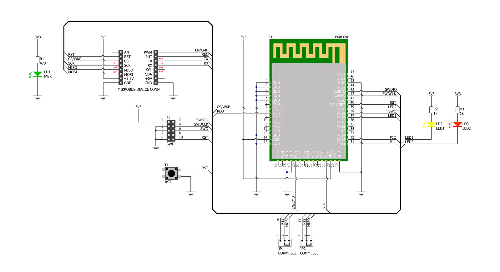
Click board™ Schematic
Step by step
Project assembly
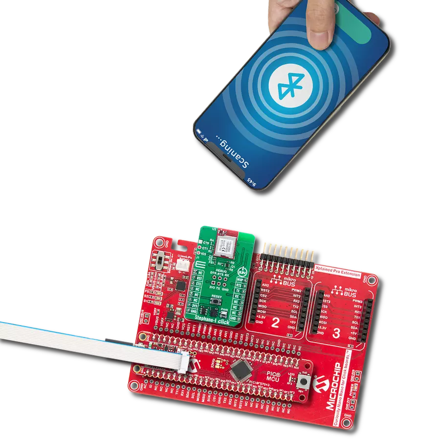
Start by selecting your development board and Click board™. Begin with the Curiosity Nano with PIC18F47K42 as your development board.


Track your results in real time
Application Output
1. Application Output - In Debug mode, the 'Application Output' window enables real-time data monitoring, offering direct insight into execution results. Ensure proper data display by configuring the environment correctly using the provided tutorial.

2. UART Terminal - Use the UART Terminal to monitor data transmission via a USB to UART converter, allowing direct communication between the Click board™ and your development system. Configure the baud rate and other serial settings according to your project's requirements to ensure proper functionality. For step-by-step setup instructions, refer to the provided tutorial.

3. Plot Output - The Plot feature offers a powerful way to visualize real-time sensor data, enabling trend analysis, debugging, and comparison of multiple data points. To set it up correctly, follow the provided tutorial, which includes a step-by-step example of using the Plot feature to display Click board™ readings. To use the Plot feature in your code, use the function: plot(*insert_graph_name*, variable_name);. This is a general format, and it is up to the user to replace 'insert_graph_name' with the actual graph name and 'variable_name' with the parameter to be displayed.

Software Support
Library Description
This library contains API for BLE 12 Click driver.
Key functions:
ble12_set_device_name- BLE 12 set device name functionble12_set_op_mode- BLE 12 set operating mode functionble12_send_cmd- BLE 12 sends the command function
Open Source
Code example
The complete application code and a ready-to-use project are available through the NECTO Studio Package Manager for direct installation in the NECTO Studio. The application code can also be found on the MIKROE GitHub account.
/*!
 * @file main.c
 * @brief BLE 12 Click Example.
 *
 * # Description
 * This example reads and processes data from BLE 12 Click board™.
 *
 * The demo application is composed of two sections :
 *
 * ## Application Init
 * Initializes UART driver and logs UART.
 * After driver initialization, the app performs a wake-up module,
 * enters command mode, sets the device name and advertising time interval,
 * and disconnects all connections.
 * After that, the blinking of the yellow LED Indicates
 * that the BLE 12 Click board™ is ready for connection.
 * After establishing the connection, the yellow LED is turned on.
 *
 * ## Application Task
 * This example demonstrates the use of the BLE 12 Click board™.
 * Reads the received data and parses it.
 * Results are being sent to the Usart Terminal, where you can track their changes.
 *
 * ## Additional Function
 * - static void ble12_clear_app_buf ( void )
 * - static err_t ble12_process ( void )
 *
 * @note
 * We have used the Serial Bluetooth Terminal Android application for the test
 * and you can find it at the link:
 * https://play.google.com/store/apps/details?id=de.kai_morich.serial_bluetooth_terminal
 *
 * @author Nenad Filipovic
 *
 */

#include "board.h"
#include "log.h"
#include "ble12.h"

#define PROCESS_BUFFER_SIZE 200
#define RSP_TIMEOUT         100

static ble12_t ble12;
static log_t logger;

static char app_buf[ PROCESS_BUFFER_SIZE ] = { 0 };
static int32_t app_buf_len = 0;
static int32_t app_buf_cnt = 0;

/**
 * @brief BLE 12 clearing application buffer.
 * @details This function clears memory of application buffer and reset it's length and counter.
 * @note None.
 */
static void ble12_clear_app_buf ( void );

/**
 * @brief BLE 12 data reading function.
 * @details This function reads data from device and concatenates data to application buffer.
 *
 * @return @li @c  0 - Read some data.
 *         @li @c -1 - Nothing is read.
 *         @li @c -2 - Application buffer overflow.
 *
 * See #err_t definition for detailed explanation.
 * @note None.
 */
static err_t ble12_process ( void );

void application_init ( void )
{
    log_cfg_t log_cfg;  /**< Logger config object. */
    ble12_cfg_t ble12_cfg;  /**< Click config object. */

    /**
     * Logger initialization.
     * Default baud rate: 115200
     * Default log level: LOG_LEVEL_DEBUG
     * @note If USB_UART_RX and USB_UART_TX
     * are defined as HAL_PIN_NC, you will
     * need to define them manually for log to work.
     * See @b LOG_MAP_USB_UART macro definition for detailed explanation.
     */
    LOG_MAP_USB_UART( log_cfg );
    log_init( &logger, &log_cfg );
    log_info( &logger, " Application Init " );

    // Click initialization.
    ble12_cfg_setup( &ble12_cfg );
    BLE12_MAP_MIKROBUS( ble12_cfg, MIKROBUS_1 );
    if ( UART_ERROR == ble12_init( &ble12, &ble12_cfg ) )
    {
        log_error( &logger, " Communication init." );
        for ( ; ; );
    }

    if ( BLE12_ERROR == ble12_default_cfg ( &ble12 ) )
    {
        log_error( &logger, " Default configuration." );
        for ( ; ; );
    }

    app_buf_len = 0;
    app_buf_cnt = 0;
    Delay_ms ( 100 );
    log_info( &logger, " Application Task " );

    log_printf( &logger, "-------------------------------\r\n" );
    log_printf( &logger, "\t  BLE 12 Click\r\n" );
    log_printf( &logger, "-------------------------------\r\n" );
    log_printf( &logger, "\t  Command mode\r\n" );
    ble12_set_op_mode( &ble12, BLE12_OP_MODE_CMD );
    Delay_ms ( 100 );

    ble12_event_startup( &ble12 );
    Delay_ms ( 100 );

    ble12_set_led_state( &ble12, BLE12_LED_RED, BLE12_LED_OFF );
    ble12_set_led_state( &ble12, BLE12_LED_YELLOW, BLE12_LED_OFF );
    Delay_ms ( 100 );

    log_printf( &logger, "- - - - - - - - - - - - - - - -\r\n" );
    log_printf( &logger, "> Set device name:" );
    log_printf( &logger, " BLE 12 Click\r\n" );
    ble12_set_device_name( &ble12, "BLE 12 Click" );
    Delay_ms ( 100 );

    log_printf( &logger, "> Set Adv. Interval: 99 ms\r\n" );
    ble12_set_adv_interval( &ble12, "0099" );
    Delay_ms ( 100 );

    log_printf( &logger, "> Disconnect all connections\r\n" );
    ble12_disconnect( &ble12 );
    Delay_ms ( 100 );

    log_printf( &logger, "-------------------------------\r\n" );
    log_printf( &logger, "  Please connect your device\r\n" );

    do
    {
        ble12_process();
        ble12_set_led_state( &ble12, BLE12_LED_YELLOW, BLE12_LED_ON );
        Delay_ms ( 50 );
        ble12_set_led_state( &ble12, BLE12_LED_YELLOW, BLE12_LED_OFF );
        Delay_ms ( 50 );
    }
    while ( !strstr( app_buf, BLE12_EVT_CONNECTED ) );
    Delay_ms ( 100 );

    ble12_set_led_state( &ble12, BLE12_LED_RED, BLE12_LED_OFF );
    ble12_set_led_state( &ble12, BLE12_LED_YELLOW, BLE12_LED_ON );
    log_printf( &logger, "- - - - - - - - - - - - - - - -\r\n" );
    log_printf( &logger, "\tDevice connected\r\n" );
    Delay_ms ( 100 );

    ble12_set_op_mode( &ble12, BLE12_OP_MODE_DATA );
    log_printf( &logger, "-------------------------------\r\n" );
    log_printf( &logger, "\t    Data mode\r\n" );
    log_printf( &logger, "- - - - - - - - - - - - - - - -\r\n" );
    Delay_ms ( 100 );

    ble12_process();
    ble12_clear_app_buf( );
    Delay_ms ( 100 );
}

void application_task ( void )
{
    ble12_process();

    if ( app_buf_len > 0 )
    {
        log_printf( &logger, "%s", app_buf );
        ble12_clear_app_buf(  );
    }
}

int main ( void )
{
    /* Do not remove this line or clock might not be set correctly. */
    #ifdef PREINIT_SUPPORTED
    preinit();
    #endif

    application_init( );

    for ( ; ; )
    {
        application_task( );
    }

    return 0;
}

static void ble12_clear_app_buf ( void )
{
    memset( app_buf, 0, app_buf_len );
    app_buf_len = 0;
    app_buf_cnt = 0;
}

static err_t ble12_process ( void )
{
    int32_t rx_size;
    char rx_buff[ PROCESS_BUFFER_SIZE ] = { 0 };

    rx_size = ble12_generic_read( &ble12, rx_buff, PROCESS_BUFFER_SIZE );

    if ( rx_size > 0 )
    {
        int32_t buf_cnt = 0;

        if ( app_buf_len + rx_size >= PROCESS_BUFFER_SIZE )
        {
            ble12_clear_app_buf(  );
            return BLE12_ERROR;
        }
        else
        {
            buf_cnt = app_buf_len;
            app_buf_len += rx_size;
        }

        for ( int32_t rx_cnt = 0; rx_cnt < rx_size; rx_cnt++ )
        {
            if ( ( rx_buff[ rx_cnt ] != 0 ) && ( rx_buff[ rx_cnt ] != 0x2B ) )
            {
                app_buf[ ( buf_cnt + rx_cnt ) ] = rx_buff[ rx_cnt ];
            }
            else
            {
                app_buf_len--;
                buf_cnt--;
            }
        }


        return BLE12_OK;
    }
    return BLE12_ERROR;
}


// ------------------------------------------------------------------------ END
Additional Support
Resources
Category:BT/BLE