Unlock the magic of Bluetooth with BGM220P and ATmega328P
Our Bluetooth marvel!
Published Feb 14, 2024
Click board™
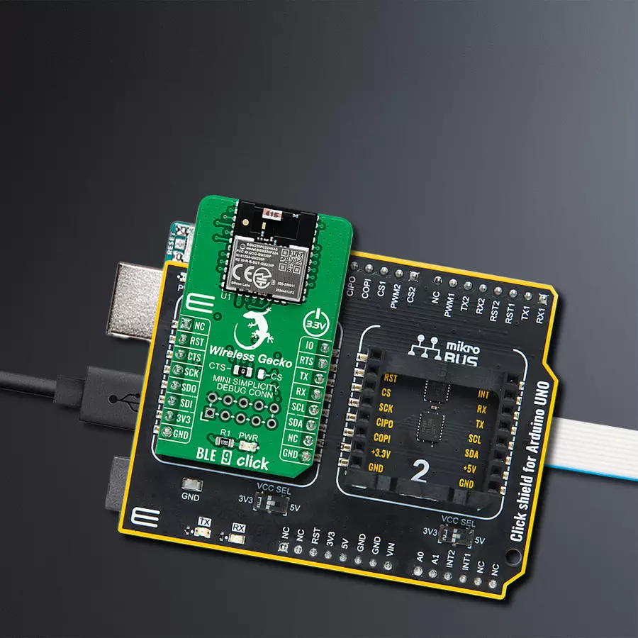
BLE 9 Click
Dev. board
Arduino UNO Rev3
Compiler
NECTO Studio
MCU
ATmega328P
Discover the true essence of wireless convenience with our advanced Bluetooth solution, connecting your devices effortlessly and eliminating the hassle of cables
A
A
Hardware Overview
How does it work?
BLE 9 Click is based on the BGM220P, an RF performance Bluetooth Low Energy solution that provides BT/BLE connectivity for any embedded application from Silicon Labs. It supports Bluetooth 5.2, direction-finding, and Bluetooth Mesh Low Power Node protocols to deliver industry-leading accuracy. It has worldwide regulatory certifications and a fully-upgradeable software stack as advanced development and debugging tool. The BGM220P module combines the EFR32BG22 wireless System on a Chip (SoC), required decoupling capacitors and inductors, 38.4 MHz and 32.768 kHz crystals, an RF matching circuit, and an integrated ceramic onboard chip antenna. The EFR32BG22 SoC, inside the BGM220P module, includes an Arm Cortex-M33 processing core, up to 32Kb of RAM, up to 512kB of flash memory, and a 2.4GHz radio transceiver, offering up to 8dB output power. This Click board™ offers enhanced performance,
security, and reliability to support IoT products running on Bluetooth networks. BLE 9 Click communicates with MCU using the UART interface as its default communication protocol with the option for the users to use other interfaces, such as SPI and I2C, if they want to configure the module and write the library by themselves using these protocols. It also can be used in a stand-alone SoC configuration without an external host processor. In addition to these protocol pins, this Click board™ also has serial UART connections labeled as CTS and RTS, routed on the CS and INT pins of the mikroBUS™ socket, as well as the Reset pin provided and routed at the RST pin of the mikroBUS™ socket. An additional GPIO pin, labeled as IO routed on the PWM pin of the mikroBUS™ socket, is left for configuration purposes as the user desires. An onboard jumper selects the function of the CS mikroBUS™ pin between the SPI or UART communication pin.
Selection is performed by positioning the SMD jumper, labeled as CTS or CS, to an appropriate position. At the bottom of the BLE 9 Click is an additional header, the Mini Simplicity Debug Connector, which fully supports debugging and programming capabilities. With this header, the user can use a serial wire debug interface for programming and debugging, using SWCLK and SWDIO pins, with a Virtual UART COM port and Virtual UART-SWD-based interface also available through the SWD interface (SWDIO, SWCLK, and SWO). This Click board™ can be operated only with a 3.3V logic voltage level. The board must perform appropriate logic voltage level conversion before using MCUs with different logic levels. Also, it comes equipped with a library containing functions and an example code that can be used, as a reference, for further development.

Features overview
Development board
Arduino UNO is a versatile microcontroller board built around the ATmega328P chip. It offers extensive connectivity options for various projects, featuring 14 digital input/output pins, six of which are PWM-capable, along with six analog inputs. Its core components include a 16MHz ceramic resonator, a USB connection, a power jack, an
ICSP header, and a reset button, providing everything necessary to power and program the board. The Uno is ready to go, whether connected to a computer via USB or powered by an AC-to-DC adapter or battery. As the first USB Arduino board, it serves as the benchmark for the Arduino platform, with "Uno" symbolizing its status as the
first in a series. This name choice, meaning "one" in Italian, commemorates the launch of Arduino Software (IDE) 1.0. Initially introduced alongside version 1.0 of the Arduino Software (IDE), the Uno has since become the foundational model for subsequent Arduino releases, embodying the platform's evolution.

Microcontroller Overview
MCU Card / MCU

Architecture
AVR
MCU Memory (KB)
32
Silicon Vendor
Microchip
Pin count
28
RAM (Bytes)
2048
You complete me!
Accessories
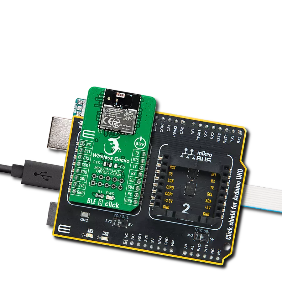
Click Shield for Arduino UNO has two proprietary mikroBUS™ sockets, allowing all the Click board™ devices to be interfaced with the Arduino UNO board without effort. The Arduino Uno, a microcontroller board based on the ATmega328P, provides an affordable and flexible way for users to try out new concepts and build prototypes with the ATmega328P microcontroller from various combinations of performance, power consumption, and features. The Arduino Uno has 14 digital input/output pins (of which six can be used as PWM outputs), six analog inputs, a 16 MHz ceramic resonator (CSTCE16M0V53-R0), a USB connection, a power jack, an ICSP header, and reset button. Most of the ATmega328P microcontroller pins are brought to the IO pins on the left and right edge of the board, which are then connected to two existing mikroBUS™ sockets. This Click Shield also has several switches that perform functions such as selecting the logic levels of analog signals on mikroBUS™ sockets and selecting logic voltage levels of the mikroBUS™ sockets themselves. Besides, the user is offered the possibility of using any Click board™ with the help of existing bidirectional level-shifting voltage translators, regardless of whether the Click board™ operates at a 3.3V or 5V logic voltage level. Once you connect the Arduino UNO board with our Click Shield for Arduino UNO, you can access hundreds of Click boards™, working with 3.3V or 5V logic voltage levels.

Used MCU Pins
mikroBUS™ mapper
Take a closer look
Click board™ Schematic

Step by step
Project assembly

Start by selecting your development board and Click board™. Begin with the Arduino UNO Rev3 as your development board.


Track your results in real time
Application Output
1. Application Output - In Debug mode, the 'Application Output' window enables real-time data monitoring, offering direct insight into execution results. Ensure proper data display by configuring the environment correctly using the provided tutorial.

2. UART Terminal - Use the UART Terminal to monitor data transmission via a USB to UART converter, allowing direct communication between the Click board™ and your development system. Configure the baud rate and other serial settings according to your project's requirements to ensure proper functionality. For step-by-step setup instructions, refer to the provided tutorial.

3. Plot Output - The Plot feature offers a powerful way to visualize real-time sensor data, enabling trend analysis, debugging, and comparison of multiple data points. To set it up correctly, follow the provided tutorial, which includes a step-by-step example of using the Plot feature to display Click board™ readings. To use the Plot feature in your code, use the function: plot(*insert_graph_name*, variable_name);. This is a general format, and it is up to the user to replace 'insert_graph_name' with the actual graph name and 'variable_name' with the parameter to be displayed.

Software Support
Library Description
This library contains API for BLE 9 Click driver.
Key functions:
ble9_adv_create_id- This function creates adequate IDble9_adv_start- This function starts advertising
Open Source
Code example
The complete application code and a ready-to-use project are available through the NECTO Studio Package Manager for direct installation in the NECTO Studio. The application code can also be found on the MIKROE GitHub account.
/*!
 * @file main.c
 * @brief BLE 9 Click example
 *
 * # Description
 * This example demonstrates the use of BLE 9 Click board by processing
 * the incoming data and displaying them on the USB UART.
 *
 * The demo application is composed of two sections :
 *
 * ## Application Init
 * Initializes the driver and performs the Click default configuration.
 *
 * ## Application Task
 * Reads and processes all incoming data and displays them on the USB UART.
 *
 * ## Additional Function
 * - static void ble9_clear_app_buf ( void )
 * - static err_t ble9_process ( ble9_t *ctx )
 *
 * <pre>
 * For more information on the chip itself and the firmware on it,
 * please visit the following page:
 *     [1] https://docs.silabs.com/bluetooth/3.1
 *         - Take into condideration that the library itself
 *           is designed to work with GSDK version 3.1.0
 *           If you wish to use a different version of firmware,
 *           take into consideration that some functions might not work.
 * </pre>
 *
 * @author MikroE Team
 */
// ------------------------------------------------------------------- INCLUDES

#include "board.h"
#include "ble9.h"
#include "log.h"

#define PROCESS_BUFFER_SIZE 200

static ble9_t ble9;
static log_t logger;

static uint8_t app_buf[ PROCESS_BUFFER_SIZE ] = { 0 };
static int32_t app_buf_len = 0;

/**
 * @brief BLE 9 clearing application buffer.
 * @details This function clears memory of application buffer and reset its length.
 * @note None.
 */
static void ble9_clear_app_buf ( void );

/**
 * @brief BLE 9 data reading function.
 * @details This function reads data from device and concatenates data to application buffer.
 * @param[in] ctx : Click context object.
 * See #ble9_t object definition for detailed explanation.
 * @return @li @c  0 - Read some data.
 *         @li @c -1 - Nothing is read.
 * See #err_t definition for detailed explanation.
 * @note None.
 */
static err_t ble9_process ( ble9_t *ctx );

// ------------------------------------------------------ APPLICATION FUNCTIONS

void application_init ( void )
{
    log_cfg_t log_cfg;
    ble9_cfg_t cfg;

    /**
     * Logger initialization.
     * Default baud rate: 115200
     * Default log level: LOG_LEVEL_DEBUG
     * @note If USB_UART_RX and USB_UART_TX
     * are defined as HAL_PIN_NC, you will
     * need to define them manually for log to work.
     * See @b LOG_MAP_USB_UART macro definition for detailed explanation.
     */
    LOG_MAP_USB_UART( log_cfg );
    log_init( &logger, &log_cfg );
    log_info( &logger, "---- Application Init ----" );
    Delay_ms ( 100 );

    // Click initialization.
    ble9_cfg_setup( &cfg );
    BLE9_MAP_MIKROBUS( cfg, MIKROBUS_1 );
    ble9_init( &ble9, &cfg );
    Delay_ms ( 1000 );

    // Clear app buffer
    ble9_process ( &ble9 );
    ble9_clear_app_buf( );
    Delay_ms ( 100 );

    if ( BLE9_OK == ble9_sys_get_version ( &ble9 ) )
    {
        log_printf( &logger, "--- System Version ---\r\n" );
        log_printf( &logger, " Major: 0x%.4X\r\n", ble9.ble9_version.version_major );
        log_printf( &logger, " Minor: 0x%.4X\r\n", ble9.ble9_version.version_minor );
        log_printf( &logger, " Patch: 0x%.4X\r\n", ble9.ble9_version.version_patch );
        log_printf( &logger, " Build: 0x%.4X\r\n", ble9.ble9_version.version_build );
        log_printf( &logger, " Bootloader: 0x%.8LX\r\n", ble9.ble9_version.version_bootloader );
        log_printf( &logger, " Hash: 0x%.8LX\r\n", ble9.ble9_version.version_hash );
        log_printf( &logger, "------------------------\r\n" );
    }

    log_printf( &logger, "Creating advertising point...\r\n" );
    Delay_ms ( 100 );
    ble9_adv_create_id ( &ble9 );

    log_printf( &logger, "Starting module advertising...\r\n" );
    Delay_ms ( 100 );
    ble9_adv_start ( &ble9, BLE9_ADVERTISER_MODE_DISCOVERABLE_GENERAL,
                     BLE9_ADVERTISER_MODE_CONNECTABLE_SCANNABLE );

    log_printf( &logger, "The module has been configured.\r\n" );
    Delay_ms ( 100 );
}

void application_task ( void )
{
    ble9_process ( &ble9 );
    if ( app_buf_len > 0 )
    {
        for ( uint16_t cnt = 0; cnt < app_buf_len; cnt++ )
        {
            log_printf( &logger, "%.2X ", ( uint16_t ) app_buf[ cnt ] );
        }
        ble9_clear_app_buf( );
    }
}

int main ( void )
{
    /* Do not remove this line or clock might not be set correctly. */
    #ifdef PREINIT_SUPPORTED
    preinit();
    #endif

    application_init( );

    for ( ; ; )
    {
        application_task( );
    }

    return 0;
}

static void ble9_clear_app_buf ( void )
{
    memset( app_buf, 0, app_buf_len );
    app_buf_len = 0;
}

static err_t ble9_process ( ble9_t *ctx )
{
    uint8_t rx_buf[ PROCESS_BUFFER_SIZE ] = { 0 };
    int32_t rx_size = 0;
    rx_size = ble9_generic_read( ctx, rx_buf, PROCESS_BUFFER_SIZE );
    if ( rx_size > 0 )
    {
        int32_t buf_cnt = app_buf_len;
        if ( ( ( app_buf_len + rx_size ) > PROCESS_BUFFER_SIZE ) && ( app_buf_len > 0 ) )
        {
            buf_cnt = PROCESS_BUFFER_SIZE - ( ( app_buf_len + rx_size ) - PROCESS_BUFFER_SIZE );
            memmove ( app_buf, &app_buf[ PROCESS_BUFFER_SIZE - buf_cnt ], buf_cnt );
        }
        for ( int32_t rx_cnt = 0; rx_cnt < rx_size; rx_cnt++ )
        {
            if ( rx_buf[ rx_cnt ] )
            {
                app_buf[ buf_cnt++ ] = rx_buf[ rx_cnt ];
                if ( app_buf_len < PROCESS_BUFFER_SIZE )
                {
                    app_buf_len++;
                }
            }
        }
        return BLE9_OK;
    }
    return BLE9_ERROR;
}

// ------------------------------------------------------------------------ END
Additional Support
Resources
Category:BT/BLE