Create solutions with innovative touch-sensitive controls using CAP1166 and ATmega328
Tap into endless possibilities
Published Feb 14, 2024
Click board™
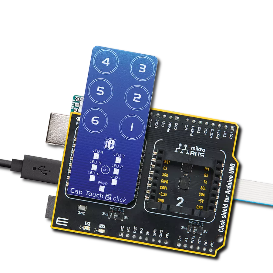
Cap Touch 2 click
Dev. board
Arduino UNO Rev3
Compiler
NECTO Studio
MCU
ATmega328
Dive into the world of capacitive touch sensing and transform your ideas into touch-sensitive reality
A
A
Hardware Overview
How does it work?
Cap Touch 2 Click is based on the CAP1166, a 6-channel capacitive touch sensor with 6 LED drivers from Microchip. This IC comprises six input capacitive touch channels, implemented with the RightTouch® technology, six LED drives with programmable signaling functions, and the logic section, which uses the standard SPI communication interface. Besides the SPI bus, the logic section uses a few more lines - for the device reset and triggering the alert (interrupt) event. The board has six PCB pads to sense touch or proximity events. These pads are the only elements on the top of the board, allowing the protective acrylic glass layer to be installed. These pads can be programmed to generate a touch event for both when they are pressed and when they are released. The capacitive sensor channels feature programmable sensitivity and an automatic recalibration, used to compensate for environmental changes. The recalibration procedure can be triggered either automatically or on-demand, and it is used to set the base register value for the “not touched” state of the input channel. The enabled input channels are polled in a cyclic order. A touch event will be generated if
the difference between the base value and the measured value on a particular channel is over the threshold. The CAP1166 IC also integrates sections that provide efficient interference protection. The EMI and RFI detection sections protect by discarding the corrupted bytes if the detected noise threshold is exceeded. Also, false input readings, such as the negative values and “stuck button” events, are handled by the internal algorithms, which will set the respective bits to indicate the problem, and can be set to trigger a recalibration procedure. Multiple touch pattern detection (MTPD) sets the pattern to generate a touch event. This pattern may consist of multiple specific sensors touched at once, a minimal number of touched sensors, or when their noise flag bit is set in the status register. This function can be used to detect a closed lid or similar event. Cap Touch 2 click contains six LEDs mounted on the back side of the PCB inside the specially designed openings. These LEDs can be linked to the corresponding sensing channel or controlled by the host MCU. As described above, these LEDs can be programmed to indicate a touch event with a range of lighting effects, including
breathing, two modes of pulsing with programmable parameters, and an ON-OFF state. The interrupt engine allows one to differentiate between simple touch and touch-and-hold events. The interrupt can be generated once when a pad touch is detected or repeatedly generated while the pad is touched. The programmable timer is started after the first touch event on a specific channel. The interrupt is generated in the programmed intervals if no release event is detected after the timer expires. This function is very useful for building volume up/down buttons, light-dimming buttons, and similar applications. The interrupt event will also drive the /ALERT pin to a state defined in the configuration register. This pin is routed to the mikroBUS™ INT pin and is used to trigger an interrupt event on the host MCU. The RST pin is routed to the RST pin of the mikroBUS™ and is used to reset the CAP1166 IC. This pin must be set to a HIGH logic level to reset the device. This will clear all the readings and reset the configuration registers to their factory default values. The device will be kept in a Deep Sleep mode until this pin is set to a LOW logic level. This pin is equipped with a pull-down resistor.


Features overview
Development board
Arduino UNO is a versatile microcontroller board built around the ATmega328P chip. It offers extensive connectivity options for various projects, featuring 14 digital input/output pins, six of which are PWM-capable, along with six analog inputs. Its core components include a 16MHz ceramic resonator, a USB connection, a power jack, an
ICSP header, and a reset button, providing everything necessary to power and program the board. The Uno is ready to go, whether connected to a computer via USB or powered by an AC-to-DC adapter or battery. As the first USB Arduino board, it serves as the benchmark for the Arduino platform, with "Uno" symbolizing its status as the
first in a series. This name choice, meaning "one" in Italian, commemorates the launch of Arduino Software (IDE) 1.0. Initially introduced alongside version 1.0 of the Arduino Software (IDE), the Uno has since become the foundational model for subsequent Arduino releases, embodying the platform's evolution.

Microcontroller Overview
MCU Card / MCU

Architecture
AVR
MCU Memory (KB)
32
Silicon Vendor
Microchip
Pin count
32
RAM (Bytes)
2048
You complete me!
Accessories
Click Shield for Arduino UNO has two proprietary mikroBUS™ sockets, allowing all the Click board™ devices to be interfaced with the Arduino UNO board without effort. The Arduino Uno, a microcontroller board based on the ATmega328P, provides an affordable and flexible way for users to try out new concepts and build prototypes with the ATmega328P microcontroller from various combinations of performance, power consumption, and features. The Arduino Uno has 14 digital input/output pins (of which six can be used as PWM outputs), six analog inputs, a 16 MHz ceramic resonator (CSTCE16M0V53-R0), a USB connection, a power jack, an ICSP header, and reset button. Most of the ATmega328P microcontroller pins are brought to the IO pins on the left and right edge of the board, which are then connected to two existing mikroBUS™ sockets. This Click Shield also has several switches that perform functions such as selecting the logic levels of analog signals on mikroBUS™ sockets and selecting logic voltage levels of the mikroBUS™ sockets themselves. Besides, the user is offered the possibility of using any Click board™ with the help of existing bidirectional level-shifting voltage translators, regardless of whether the Click board™ operates at a 3.3V or 5V logic voltage level. Once you connect the Arduino UNO board with our Click Shield for Arduino UNO, you can access hundreds of Click boards™, working with 3.3V or 5V logic voltage levels.

Used MCU Pins
mikroBUS™ mapper
Take a closer look
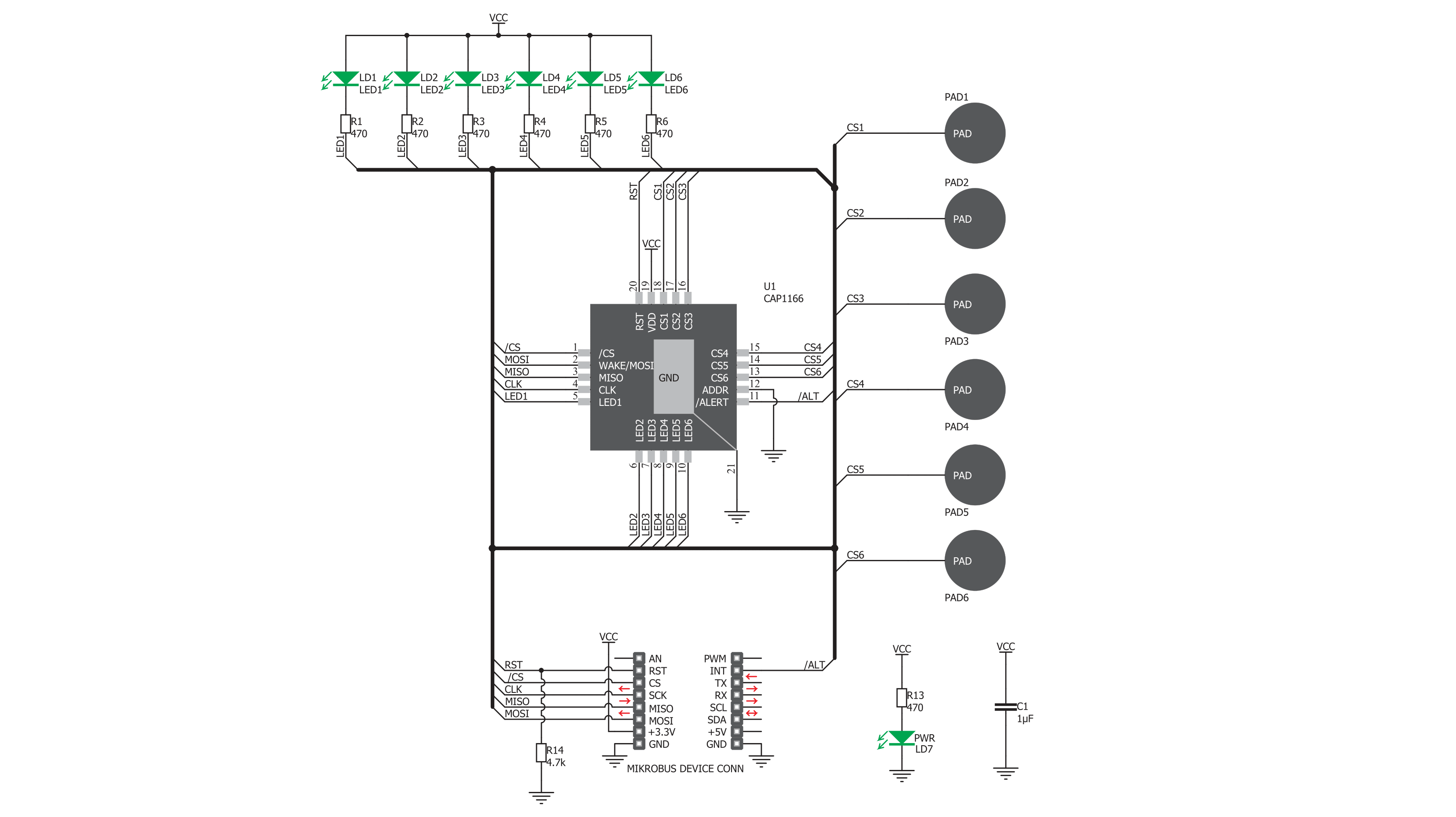
Click board™ Schematic
Step by step
Project assembly

Start by selecting your development board and Click board™. Begin with the Arduino UNO Rev3 as your development board.


Track your results in real time
Application Output
1. Application Output - In Debug mode, the 'Application Output' window enables real-time data monitoring, offering direct insight into execution results. Ensure proper data display by configuring the environment correctly using the provided tutorial.

2. UART Terminal - Use the UART Terminal to monitor data transmission via a USB to UART converter, allowing direct communication between the Click board™ and your development system. Configure the baud rate and other serial settings according to your project's requirements to ensure proper functionality. For step-by-step setup instructions, refer to the provided tutorial.

3. Plot Output - The Plot feature offers a powerful way to visualize real-time sensor data, enabling trend analysis, debugging, and comparison of multiple data points. To set it up correctly, follow the provided tutorial, which includes a step-by-step example of using the Plot feature to display Click board™ readings. To use the Plot feature in your code, use the function: plot(*insert_graph_name*, variable_name);. This is a general format, and it is up to the user to replace 'insert_graph_name' with the actual graph name and 'variable_name' with the parameter to be displayed.

Software Support
Library Description
This library contains API for Cap Touch 2 Click driver.
Key functions:
captouch2_detect_touch- Touch Detect functioncaptouch2_check_interrupt- Interrupt Check functioncaptouch2_reset- Reset function
Open Source
Code example
The complete application code and a ready-to-use project are available through the NECTO Studio Package Manager for direct installation in the NECTO Studio. The application code can also be found on the MIKROE GitHub account.
/*!
 * \file
 * \brief CapTouch2 Click example
 *
 * # Description
 * The demo application shows the button reading and checking.
 *
 * The demo application is composed of two sections :
 *
 * ## Application Init
 * Configuring Clicks and log objects.
 * Reset device and settings the Click in the default configuration.
 *
 * ## Application Task
 * Calls function to check touch detection (is interrupt occured) and shows message on
 * USB UART on which input touch is detected or on which input touch is released.
 * Also turns on LED on which linked input interrupt occured.
 *
 * \author Katarina Perendic
 *
 */
// ------------------------------------------------------------------- INCLUDES

#include "board.h"
#include "log.h"
#include "captouch2.h"

// ------------------------------------------------------------------ VARIABLES

static captouch2_t captouch2;
static log_t logger;

// ------------------------------------------------------ APPLICATION FUNCTIONS

void application_init ( void )
{
    log_cfg_t log_cfg;
    captouch2_cfg_t cfg;

    /**
     * Logger initialization.
     * Default baud rate: 115200
     * Default log level: LOG_LEVEL_DEBUG
     * @note If USB_UART_RX and USB_UART_TX
     * are defined as HAL_PIN_NC, you will
     * need to define them manually for log to work.
     * See @b LOG_MAP_USB_UART macro definition for detailed explanation.
     */
    LOG_MAP_USB_UART( log_cfg );
    log_init( &logger, &log_cfg );
    log_info( &logger, "---- Application Init ----" );

    //  Click initialization.

    captouch2_cfg_setup( &cfg );
    CAPTOUCH2_MAP_MIKROBUS( cfg, MIKROBUS_1 );
    captouch2_init( &captouch2, &cfg );

    captouch2_reset( &captouch2 );
    Delay_ms ( 200 );
    captouch2_default_cfg( &captouch2 );
    Delay_ms ( 100 );
    log_info( &logger, ">> Cap Touch 2 is initialized " );
}

void application_task ( void )
{
    uint8_t cnt;
    uint8_t sensor_results[ 6 ];

    captouch2_detect_touch( &captouch2, &sensor_results[ 0 ] );
    for ( cnt = 0; cnt < 6; cnt++ )
    {
        if ( sensor_results[ cnt ] == 1 )
        {
            log_printf( &logger, "Input %d is touchedr\r\n", cnt + 1 );
        }
        else if ( sensor_results[ cnt ] == 2 )
        {
            log_printf( &logger, "Input %d is released\r\n", cnt + 1 );
        }
    }
}

int main ( void )
{
    /* Do not remove this line or clock might not be set correctly. */
    #ifdef PREINIT_SUPPORTED
    preinit();
    #endif

    application_init( );

    for ( ; ; )
    {
        application_task( );
    }

    return 0;
}


// ------------------------------------------------------------------------ END
Additional Support
Resources
Category:Capacitive


