Maintain optimal humidity levels and protect your space from damage with SHT40, SGP40 and ATmega328P
Empowering healthier homes
Published Feb 14, 2024
Click board™
Environment 2 Click
Dev. board
Arduino UNO Rev3
Compiler
NECTO Studio
MCU
ATmega328P
Create a healthier living environment by actively monitoring humidity levels and air quality parameters, ensuring the well-being of you and your loved ones
A
A
Hardware Overview
How does it work?
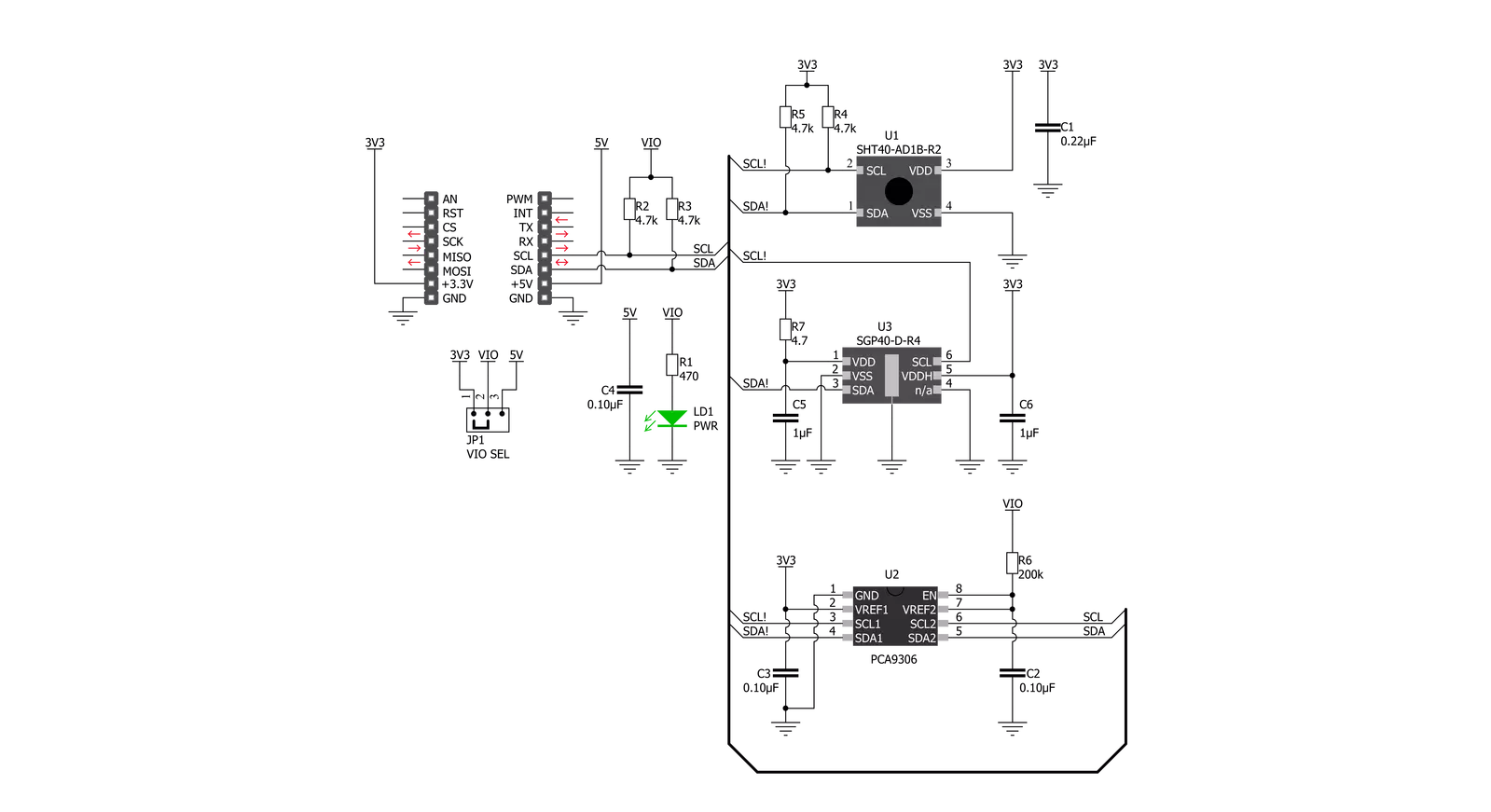
Environment 2 Click is based on the SHT40 and SGP40, a high-accuracy best-in-class SHT relative humidity, and a temperature sensor combined with MOx based gas sensor from Sensirion. The SHT40 offers reduced power consumption, improved accuracy specifications, and a fully calibrated digital I2C Fast Mode Plus interface for the fastest data transfer. It covers extended operating humidity and temperature ranges from 0 to 100%RH and from -40°C to 125°C with accuracies of ±1.8%RH and ±0.2°C. Conversely, an additional gas sensor of this combo solution, the SGP40, provides a humidity-compensated VOC-based indoor air quality signal and a temperature-controlled micro hot plate. The SHT40 performs best when operated within the recommended
average temperature and humidity range of 5-60°C and 20-80%RH. Long-term exposure to conditions outside recommended normal range, especially at high relative humidity, may temporarily offset the RH signal. After returning to the recommended average temperature and humidity range, the sensor will recover to within specifications. The output signal of the SGP40 is processed by Sensirion’s VOC Algorithm, which automatically adapts to the environment the sensor is exposed to translate the raw signal into a VOC Index. The sensing element and VOC Algorithm feature unmatched robustness against contaminating gases in real-world applications, enabling exceptional long-term stability, low drift, high reproducibility, and reliability. Environment 2
Click communicates with MCU using the standard I2C 2-Wire interface. Since both sensors for operation requires a 3.3V logic voltage level only, this Click board™ also features the PCA9306 voltage-level translator from Texas Instruments. The I2C interface bus lines are routed to the dual bidirectional voltage-level translator, allowing this Click board™ to work properly with both 3.3V and 5V MCUs. This Click board™ can operate with either 3.3V or 5V logic voltage levels selected via the VIO SEL jumper. This way, both 3.3V and 5V capable MCUs can use the communication lines properly. Also, this Click board™ comes equipped with a library containing easy-to-use functions and an example code that can be used, as a reference, for further development.


Features overview
Development board
Arduino UNO is a versatile microcontroller board built around the ATmega328P chip. It offers extensive connectivity options for various projects, featuring 14 digital input/output pins, six of which are PWM-capable, along with six analog inputs. Its core components include a 16MHz ceramic resonator, a USB connection, a power jack, an
ICSP header, and a reset button, providing everything necessary to power and program the board. The Uno is ready to go, whether connected to a computer via USB or powered by an AC-to-DC adapter or battery. As the first USB Arduino board, it serves as the benchmark for the Arduino platform, with "Uno" symbolizing its status as the
first in a series. This name choice, meaning "one" in Italian, commemorates the launch of Arduino Software (IDE) 1.0. Initially introduced alongside version 1.0 of the Arduino Software (IDE), the Uno has since become the foundational model for subsequent Arduino releases, embodying the platform's evolution.

Microcontroller Overview
MCU Card / MCU

Architecture
AVR
MCU Memory (KB)
32
Silicon Vendor
Microchip
Pin count
28
RAM (Bytes)
2048
You complete me!
Accessories
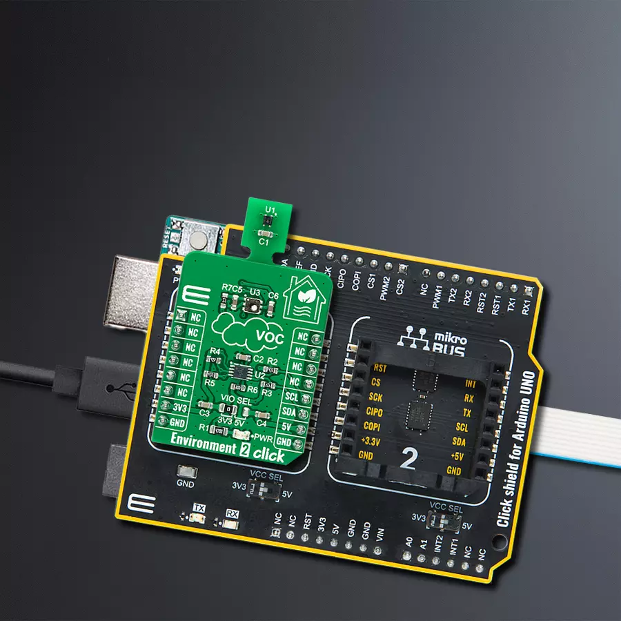
Click Shield for Arduino UNO has two proprietary mikroBUS™ sockets, allowing all the Click board™ devices to be interfaced with the Arduino UNO board without effort. The Arduino Uno, a microcontroller board based on the ATmega328P, provides an affordable and flexible way for users to try out new concepts and build prototypes with the ATmega328P microcontroller from various combinations of performance, power consumption, and features. The Arduino Uno has 14 digital input/output pins (of which six can be used as PWM outputs), six analog inputs, a 16 MHz ceramic resonator (CSTCE16M0V53-R0), a USB connection, a power jack, an ICSP header, and reset button. Most of the ATmega328P microcontroller pins are brought to the IO pins on the left and right edge of the board, which are then connected to two existing mikroBUS™ sockets. This Click Shield also has several switches that perform functions such as selecting the logic levels of analog signals on mikroBUS™ sockets and selecting logic voltage levels of the mikroBUS™ sockets themselves. Besides, the user is offered the possibility of using any Click board™ with the help of existing bidirectional level-shifting voltage translators, regardless of whether the Click board™ operates at a 3.3V or 5V logic voltage level. Once you connect the Arduino UNO board with our Click Shield for Arduino UNO, you can access hundreds of Click boards™, working with 3.3V or 5V logic voltage levels.

Used MCU Pins
mikroBUS™ mapper
Take a closer look
Click board™ Schematic
Step by step
Project assembly

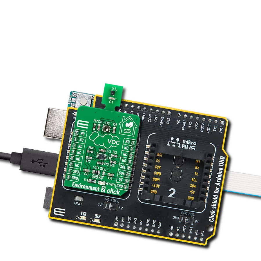
Start by selecting your development board and Click board™. Begin with the Arduino UNO Rev3 as your development board.


Track your results in real time
Application Output
1. Application Output - In Debug mode, the 'Application Output' window enables real-time data monitoring, offering direct insight into execution results. Ensure proper data display by configuring the environment correctly using the provided tutorial.

2. UART Terminal - Use the UART Terminal to monitor data transmission via a USB to UART converter, allowing direct communication between the Click board™ and your development system. Configure the baud rate and other serial settings according to your project's requirements to ensure proper functionality. For step-by-step setup instructions, refer to the provided tutorial.

3. Plot Output - The Plot feature offers a powerful way to visualize real-time sensor data, enabling trend analysis, debugging, and comparison of multiple data points. To set it up correctly, follow the provided tutorial, which includes a step-by-step example of using the Plot feature to display Click board™ readings. To use the Plot feature in your code, use the function: plot(*insert_graph_name*, variable_name);. This is a general format, and it is up to the user to replace 'insert_graph_name' with the actual graph name and 'variable_name' with the parameter to be displayed.

Software Support
Library Description
This library contains API for Environment 2 Click driver.
Key functions:
environment2_get_temp_hum- Environment 2 get temperature and relative humidity functionenvironment2_get_air_quality- Environment 2 get air quality data functionenvironment2_sgp40_measure_test- Environment 2 SGP40 measurement test function
Open Source
Code example
The complete application code and a ready-to-use project are available through the NECTO Studio Package Manager for direct installation in the NECTO Studio. The application code can also be found on the MIKROE GitHub account.
/*!
 * @file main.c
 * @brief Environment2 Click example
 *
 * # Description
 * This library contains API for Environment 2 Click driver.
 * The library contains drivers for measuring air quality,
 * temperature and relative humidity.
 *
 * The demo application is composed of two sections :
 *
 * ## Application Init
 * Initializes I2C driver and triggers the built-in self-test checking,
 * set heater off, performs sensors configuration and initialize VOC algorithm.
 *
 * ## Application Task
 * This is an example that demonstrates the use of the Environment 2 Click board.
 * Measured and display air quality ( raw data ),
 * temperature ( degrees Celsius ), relative humidity ( % ) and VOC Index.
 * Results are being sent to the Usart Terminal where you can track their changes.
 * All data logs write on USB UART changes every 2 sec.
 *
 * @author Nenad Filipovic
 *
 */

#include "board.h"
#include "log.h"
#include "environment2.h"

static environment2_t environment2;
static log_t logger;

static uint16_t air_quality;
static float humidity;
static float temperature;
static int32_t voc_index;
static environment2_voc_algorithm_params voc_algorithm_params;

void application_init ( void ) {
    log_cfg_t log_cfg;                    /**< Logger config object. */
    environment2_cfg_t environment2_cfg;  /**< Click config object. */

    /**
     * Logger initialization.
     * Default baud rate: 115200
     * Default log level: LOG_LEVEL_DEBUG
     * @note If USB_UART_RX and USB_UART_TX
     * are defined as HAL_PIN_NC, you will
     * need to define them manually for log to work.
     * See @b LOG_MAP_USB_UART macro definition for detailed explanation.
     */
    LOG_MAP_USB_UART( log_cfg );
    log_init( &logger, &log_cfg );
    log_info( &logger, " Application Init " );

    // Click initialization.

    environment2_cfg_setup( &environment2_cfg );
    ENVIRONMENT2_MAP_MIKROBUS( environment2_cfg, MIKROBUS_1 );
    err_t init_flag = environment2_init( &environment2, &environment2_cfg );
    if ( init_flag == I2C_MASTER_ERROR ) {
        log_error( &logger, " Application Init Error. " );
        log_printf( &logger, " Please, run program again... " );

        for ( ; ; );
    }

    log_printf( &logger, "    Application Task   \r\n" );
    log_printf( &logger, "-----------------------\r\n" );
    log_printf( &logger, "  Environment 2 Click  \r\n" );
    log_printf( &logger, "-----------------------\r\n" );

    if ( environment2_sgp40_measure_test( &environment2 ) == ENVIRONMENT2_SGP40_TEST_PASSED ) {
        log_printf( &logger, "    All tests passed\r\n" );
        log_printf( &logger, "      Successfully\r\n" );
    } else {
        log_printf( &logger, "    One or more tests have\r\n" );
        log_printf( &logger, "     Failed\r\n" );
    }
    log_printf( &logger, "-----------------------\r\n" );
    Delay_ms ( 100 );

    environment2_sgp40_heater_off( &environment2 );
    Delay_ms ( 100 );

    environment2_config_sensors( );
    Delay_ms ( 100 );
}

void application_task ( void ) {
    environment2_get_temp_hum(  &environment2, &humidity, &temperature );
    Delay_ms ( 100 );

    log_printf( &logger, " Humidity    : %.2f %% \r\n", humidity );
    log_printf( &logger, " Temperature : %.2f C \r\n", temperature );

    environment2_get_air_quality( &environment2, &air_quality );
    Delay_ms ( 100 );

    log_printf( &logger, " Air Quality : %d \r\n", air_quality );
    log_printf( &logger, "- - - - - - - - - -  - \r\n" );

    environment2_get_voc_index( &environment2, &voc_index );
    Delay_ms ( 100 );

    log_printf( &logger, " VOC Index   : %d  \r\n", ( uint16_t ) voc_index );
    log_printf( &logger, "-----------------------\r\n" );
    Delay_ms ( 1000 );
    Delay_ms ( 1000 );
}

int main ( void )
{
    /* Do not remove this line or clock might not be set correctly. */
    #ifdef PREINIT_SUPPORTED
    preinit();
    #endif

    application_init( );

    for ( ; ; )
    {
        application_task( );
    }

    return 0;
}

// ------------------------------------------------------------------------ END
Additional Support
Resources
Category:Environmental