Manage currents seamlessly across diverse applications with ACS723 and ATmega328P
Excellence with every Ampere
Published Feb 14, 2024
Click board™
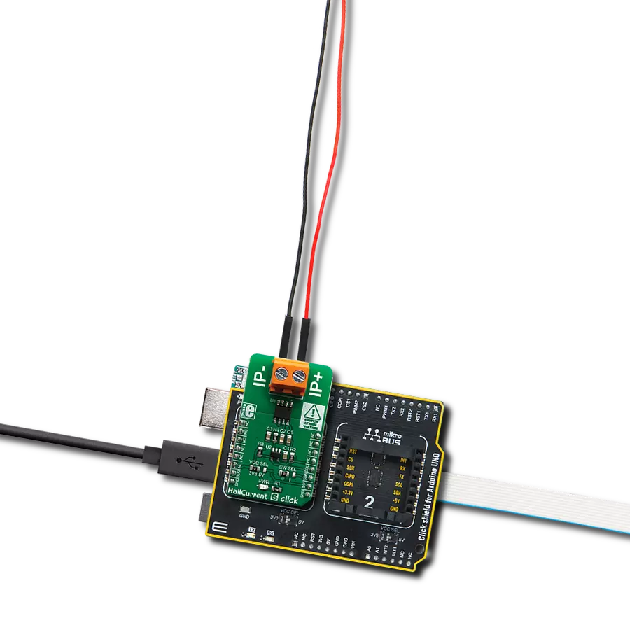
Hall Current 6 Click
Dev. board
Arduino UNO Rev3
Compiler
NECTO Studio
MCU
ATmega328P
Engineered for efficiency enhancement, our current measurement solution provides dependable monitoring, seamless management, and insightful analysis of currents across applications
A
A
Hardware Overview
How does it work?
Hall Current 6 Click is based on the ACS723, a high-accuracy, galvanically isolated current sensor IC from Allegro Microsystems. This sensor utilizes the Hall effect phenomenon to measure the current passing through the internally fused input pins of the IC. This allows the series resistance to stay very low. Current through the input rails of the IC generates a magnetic field, causing the Hall effect on the current through the integrated sensor. These two current circuits are completely isolated, with the basic isolation working voltage of about 297VRMS, allowing the Click board™ to be used in high-side current sensing applications. The output voltage changes linearly with the current in the primary circuit, with the ratio of 400mV/A, and it is fed to the MCP3221, a 12-bit analog to digital converter (ADC) with I2C interface, from Microchip. This is a well-established converter used in many Click board™ designs, thanks to its proven reliability, reasonably good sampling rate well suited for instrumentation applications (22.3 kbps),
and simplicity of use. It converts the output voltage from the ACS723 into a digital value, which is available over the I2C interface. The output voltage of the ACS723 has a very linear dependency on the current through the primary pins due to Allegro's patented digital temperature compensation. Although it can be used in a rather limited current range of ±5A, it has a great accuracy of ±3% (referred to as a Total Output Error in the datasheet). The ACS723 IC features a bandwidth selection pin, which allows the bandwidth selection according to the application it is used in. For example, when measuring current in some applications that operate at lower frequencies, limiting the bandwidth improves the noise performance, enabling to obtain results with higher accuracy. The bandwidth selection pin acts as a filter on the measurement line, allowing two cutoff frequencies: 20kHz and 80kHz. The BW_SEL pin of the ACS723 is routed to the small SMD jumper, labeled as BW SEL. When the jumper is at position
0, the device's bandwidth is 80kHz. The secondary side of the ACS733 is powered by the 5V mikroBUS™ rail. As explained earlier, current flowing through the primary conductors is galvanically isolated from the rest of the IC, protecting low-voltage parts of the Click board™, as well as the host MCU. The Click board™ should be connected in series with the load through which the current is measured using the load connector labeled with IP+ and IP-. A low internal resistance of only 0.65 mΩ across the primary conductors will not disturb the current through the circuit, so the Click board™ will not introduce its error into the measurement, thus acting as a nearly-perfect ammeter. The voltage at which the I2C lines are pulled up can be selected using the VCC SEL jumper. Selecting the logic voltage level allows this Click board™ to be interfaced with a wide range of MCUs operating at 3.3V and 5V.


Features overview
Development board
Arduino UNO is a versatile microcontroller board built around the ATmega328P chip. It offers extensive connectivity options for various projects, featuring 14 digital input/output pins, six of which are PWM-capable, along with six analog inputs. Its core components include a 16MHz ceramic resonator, a USB connection, a power jack, an
ICSP header, and a reset button, providing everything necessary to power and program the board. The Uno is ready to go, whether connected to a computer via USB or powered by an AC-to-DC adapter or battery. As the first USB Arduino board, it serves as the benchmark for the Arduino platform, with "Uno" symbolizing its status as the
first in a series. This name choice, meaning "one" in Italian, commemorates the launch of Arduino Software (IDE) 1.0. Initially introduced alongside version 1.0 of the Arduino Software (IDE), the Uno has since become the foundational model for subsequent Arduino releases, embodying the platform's evolution.

Microcontroller Overview
MCU Card / MCU

Architecture
AVR
MCU Memory (KB)
32
Silicon Vendor
Microchip
Pin count
28
RAM (Bytes)
2048
You complete me!
Accessories
Click Shield for Arduino UNO has two proprietary mikroBUS™ sockets, allowing all the Click board™ devices to be interfaced with the Arduino UNO board without effort. The Arduino Uno, a microcontroller board based on the ATmega328P, provides an affordable and flexible way for users to try out new concepts and build prototypes with the ATmega328P microcontroller from various combinations of performance, power consumption, and features. The Arduino Uno has 14 digital input/output pins (of which six can be used as PWM outputs), six analog inputs, a 16 MHz ceramic resonator (CSTCE16M0V53-R0), a USB connection, a power jack, an ICSP header, and reset button. Most of the ATmega328P microcontroller pins are brought to the IO pins on the left and right edge of the board, which are then connected to two existing mikroBUS™ sockets. This Click Shield also has several switches that perform functions such as selecting the logic levels of analog signals on mikroBUS™ sockets and selecting logic voltage levels of the mikroBUS™ sockets themselves. Besides, the user is offered the possibility of using any Click board™ with the help of existing bidirectional level-shifting voltage translators, regardless of whether the Click board™ operates at a 3.3V or 5V logic voltage level. Once you connect the Arduino UNO board with our Click Shield for Arduino UNO, you can access hundreds of Click boards™, working with 3.3V or 5V logic voltage levels.

Used MCU Pins
mikroBUS™ mapper
Take a closer look
Click board™ Schematic

Step by step
Project assembly

Start by selecting your development board and Click board™. Begin with the Arduino UNO Rev3 as your development board.


Track your results in real time
Application Output
1. Application Output - In Debug mode, the 'Application Output' window enables real-time data monitoring, offering direct insight into execution results. Ensure proper data display by configuring the environment correctly using the provided tutorial.

2. UART Terminal - Use the UART Terminal to monitor data transmission via a USB to UART converter, allowing direct communication between the Click board™ and your development system. Configure the baud rate and other serial settings according to your project's requirements to ensure proper functionality. For step-by-step setup instructions, refer to the provided tutorial.

3. Plot Output - The Plot feature offers a powerful way to visualize real-time sensor data, enabling trend analysis, debugging, and comparison of multiple data points. To set it up correctly, follow the provided tutorial, which includes a step-by-step example of using the Plot feature to display Click board™ readings. To use the Plot feature in your code, use the function: plot(*insert_graph_name*, variable_name);. This is a general format, and it is up to the user to replace 'insert_graph_name' with the actual graph name and 'variable_name' with the parameter to be displayed.

Software Support
Library Description
This library contains API for Hall Current 6 Click driver.
Key functions:
hallcurrent6_read_data- Reads ADC current datahallcurrent6_get_current- Reads current datahallcurrent6_generic_read- Generic read function
Open Source
Code example
The complete application code and a ready-to-use project are available through the NECTO Studio Package Manager for direct installation in the NECTO Studio. The application code can also be found on the MIKROE GitHub account.
/*!
 * \file
 * \brief HallCurrent6 Click example
 *
 * # Description
 * This application reads current data.
 *
 * The application is composed of two sections :
 *
 * ## Application Init
 * Initializations driver init
 *
 * ## Application Task
 * Reads Current data in mA and logs this data to USBUART every 1 sec.
 *
 *
 * \author MikroE Team
 *
 */
// ------------------------------------------------------------------- INCLUDES

#include "board.h"
#include "log.h"
#include "hallcurrent6.h"

// ------------------------------------------------------------------ VARIABLES

static hallcurrent6_t hallcurrent6;
static log_t logger;

// ------------------------------------------------------ APPLICATION FUNCTIONS

void application_init ( void )
{
    log_cfg_t log_cfg;
    hallcurrent6_cfg_t cfg;

    /**
     * Logger initialization.
     * Default baud rate: 115200
     * Default log level: LOG_LEVEL_DEBUG
     * @note If USB_UART_RX and USB_UART_TX
     * are defined as HAL_PIN_NC, you will
     * need to define them manually for log to work.
     * See @b LOG_MAP_USB_UART macro definition for detailed explanation.
     */
    LOG_MAP_USB_UART( log_cfg );
    log_init( &logger, &log_cfg );
    log_info( &logger, "---- Application Init ----" );

    //  Click initialization.

    hallcurrent6_cfg_setup( &cfg );
    HALLCURRENT6_MAP_MIKROBUS( cfg, MIKROBUS_1 );
    hallcurrent6_init( &hallcurrent6, &cfg );

    log_printf( &logger, "---- App Init Done ----\r\n" );
}

void application_task ( void )
{
    float current;

    current = hallcurrent6_get_current( &hallcurrent6 );
    log_printf( &logger, " Current value: %.2f mA \r\n" , current);
    Delay_ms ( 1000 );
}

int main ( void )
{
    /* Do not remove this line or clock might not be set correctly. */
    #ifdef PREINIT_SUPPORTED
    preinit();
    #endif

    application_init( );

    for ( ; ; )
    {
        application_task( );
    }

    return 0;
}

// ------------------------------------------------------------------------ END
Additional Support
Resources
Category:Current sensor