Capture ultra-precise acceleration data and detect electric charge variations with LIS2DUXS12 and ATmega328P
Precise acceleration measurement and electric charge variation detection

Published Apr 30, 2024
Click board™
Accel&Qvar Click
Dev. board
Arduino UNO Rev3
Compiler
NECTO Studio
MCU
ATmega328P
Designed for precise acceleration measurements and electric charge detection, ideal for developing smart devices and IoT applications.
A
A
Hardware Overview
How does it work?
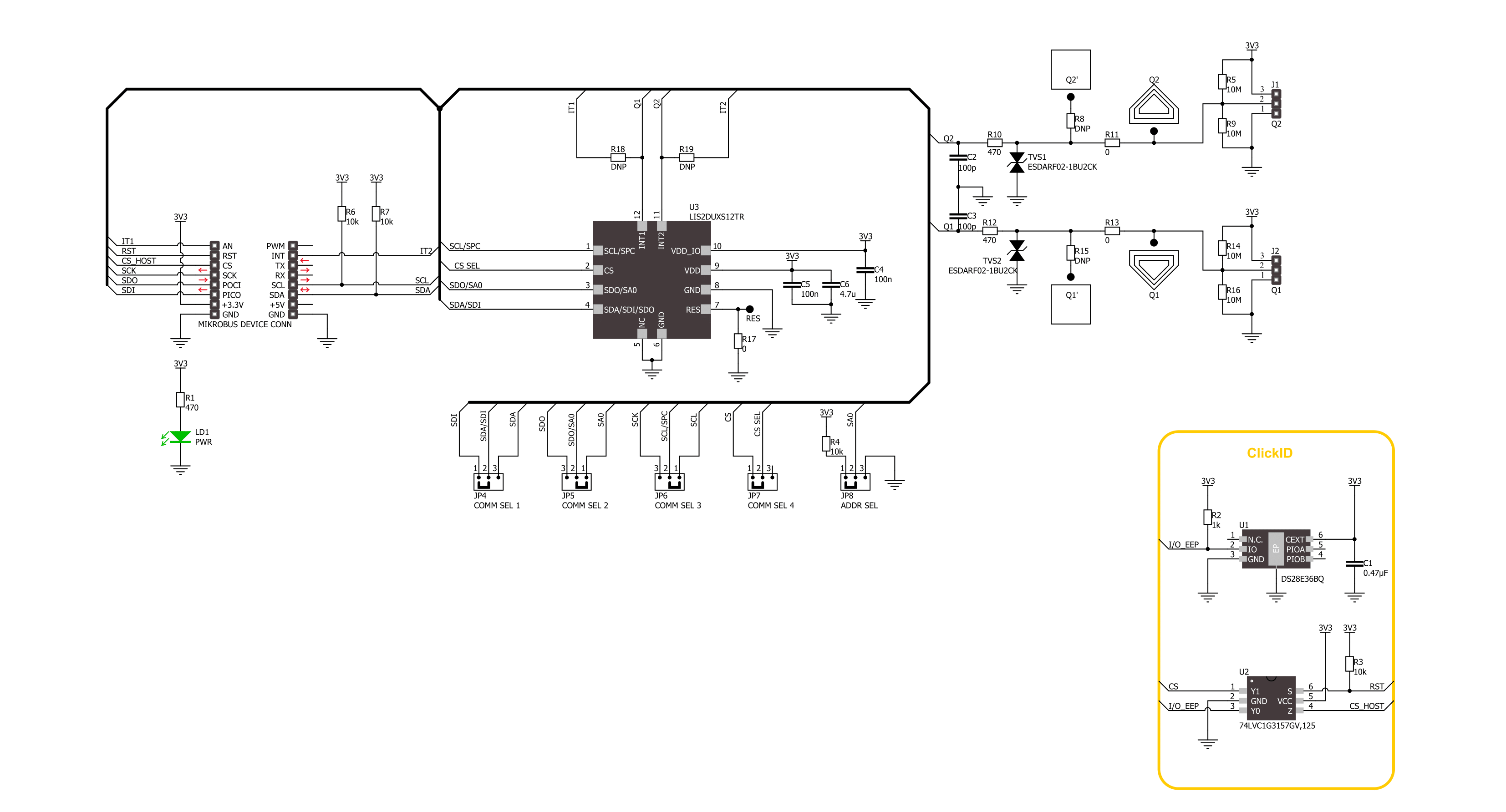
Accel&Qvar Click is based on the LIS2DUXS12, an ultralow-power accelerometer from STMicroelectronics, which is notable for its integration of Qvar technology, artificial intelligence, and an anti-aliasing filter. This component stands out due to its design, which minimizes power consumption while incorporating advanced functionalities. Embedded within the LIS2DUXS12 is a digital, 3-axis accelerometer that merges MEMS and ASIC technologies to feature an array of capabilities, including an always-on anti-aliasing filter, a finite state machine (FSM), and a machine learning core (MLC) equipped with adaptive self-configuration (ASC). Additionally, it houses an analog hub alongside a Qvar sensing channel. Including the FSM and MLC with ASC equips the LIS2DUXS12 with superior edge processing capabilities. Meanwhile, the analog hub and Qvar sensing channel pave the way for unparalleled system optimization. The LIS2DUXS12 offers adjustable full scales of ±2g, ±4g, ±8g, and ±16g and can accurately measure accelerations with output data rates (ODR) ranging from 1.6Hz to 800Hz. Its built-in engine handles motion and acceleration detections, such as free-fall, wake-up events, and multiple tap recognitions, alongside activity/inactivity monitoring and orientation detection. Operating modes of the
LIS2DUXS12 include high-performance, low-power, ultralow-power, and one-shot, ensuring versatility across different applications. Notably, its low-power mode engages a robust anti-aliasing filter, maintaining low energy consumption. These features make it ideal for various applications, including wearable technology, portable healthcare devices, and motion-activated user interfaces. As mentioned, the LIS2DUXS12 embeds a Qvar sensor that detects electric charge variations in the proximity of the external electrodes connected to the device, in this case, two sets of pads. The upper pair can be used as a radar and is disabled by default. You can enable it by soldering two unpopulated R8 and R15 0 Ohm resistors. Two arrow-like pads are parts of a sensitive touch interface able to detect touch, press, or swipe. Two 3-pin headers allow you to attach external electrodes on the sensor's Q1 and Q2 Qvar channels. These electrodes can be used for all the mentioned Qvar functionalities. This Click board™ can communicate with the host MCU by selecting one between the I2C and SPI interfaces over the COMM SEL jumper, where the I2C is selected by default. All four jumpers must be set into the appropriate position for this Click board™ to work properly. The standard 2-Wire I2C interface supports Fast mode (400kHz) and Fast mode plus
(1MHz) clock frequencies. The I2C address can be selected over the ADDR SEL jumper, where 0 is set by default. If your choice is the SPI, this Click board™ supports both 3- and 4-Wire SPI serial interfaces with clock frequencies up to 10MHz. The device may be configured to generate interrupt signals from an independent inertial wake-up/free-fall event or from the device's position. The thresholds and timing of this interrupt generator are programmable by the end user in runtime. Automatic programmable sleep-to-wake-up and return-to-sleep functions are also available for enhanced power saving. The device interrupts signal can behave as free-fall (3-axis under-threshold recognition), wake-up (axis recognition), wake-to-sleep (change of state recognition active-sleep also known as activity-inactivity), 6D and 4D orientation detection (change of position recognition), Tap-tap: single, double, triple axis and sign recognition. To use this feature on IT1 and IT2 pins, populate R18 and R19 resistors, which are unpopulated by default. This Click board™ can be operated only with a 3.3V logic voltage level. The board must perform appropriate logic voltage level conversion before using MCUs with different logic levels. Also, it comes equipped with a library containing functions and an example code that can be used as a reference for further development.

Features overview
Development board
Arduino UNO is a versatile microcontroller board built around the ATmega328P chip. It offers extensive connectivity options for various projects, featuring 14 digital input/output pins, six of which are PWM-capable, along with six analog inputs. Its core components include a 16MHz ceramic resonator, a USB connection, a power jack, an
ICSP header, and a reset button, providing everything necessary to power and program the board. The Uno is ready to go, whether connected to a computer via USB or powered by an AC-to-DC adapter or battery. As the first USB Arduino board, it serves as the benchmark for the Arduino platform, with "Uno" symbolizing its status as the
first in a series. This name choice, meaning "one" in Italian, commemorates the launch of Arduino Software (IDE) 1.0. Initially introduced alongside version 1.0 of the Arduino Software (IDE), the Uno has since become the foundational model for subsequent Arduino releases, embodying the platform's evolution.

Microcontroller Overview
MCU Card / MCU

Architecture
AVR
MCU Memory (KB)
32
Silicon Vendor
Microchip
Pin count
28
RAM (Bytes)
2048
You complete me!
Accessories
Click Shield for Arduino UNO has two proprietary mikroBUS™ sockets, allowing all the Click board™ devices to be interfaced with the Arduino UNO board without effort. The Arduino Uno, a microcontroller board based on the ATmega328P, provides an affordable and flexible way for users to try out new concepts and build prototypes with the ATmega328P microcontroller from various combinations of performance, power consumption, and features. The Arduino Uno has 14 digital input/output pins (of which six can be used as PWM outputs), six analog inputs, a 16 MHz ceramic resonator (CSTCE16M0V53-R0), a USB connection, a power jack, an ICSP header, and reset button. Most of the ATmega328P microcontroller pins are brought to the IO pins on the left and right edge of the board, which are then connected to two existing mikroBUS™ sockets. This Click Shield also has several switches that perform functions such as selecting the logic levels of analog signals on mikroBUS™ sockets and selecting logic voltage levels of the mikroBUS™ sockets themselves. Besides, the user is offered the possibility of using any Click board™ with the help of existing bidirectional level-shifting voltage translators, regardless of whether the Click board™ operates at a 3.3V or 5V logic voltage level. Once you connect the Arduino UNO board with our Click Shield for Arduino UNO, you can access hundreds of Click boards™, working with 3.3V or 5V logic voltage levels.

Used MCU Pins
mikroBUS™ mapper
Take a closer look
Click board™ Schematic
Step by step
Project assembly

Start by selecting your development board and Click board™. Begin with the Arduino UNO Rev3 as your development board.


Track your results in real time
Application Output
1. Application Output - In Debug mode, the 'Application Output' window enables real-time data monitoring, offering direct insight into execution results. Ensure proper data display by configuring the environment correctly using the provided tutorial.

2. UART Terminal - Use the UART Terminal to monitor data transmission via a USB to UART converter, allowing direct communication between the Click board™ and your development system. Configure the baud rate and other serial settings according to your project's requirements to ensure proper functionality. For step-by-step setup instructions, refer to the provided tutorial.

3. Plot Output - The Plot feature offers a powerful way to visualize real-time sensor data, enabling trend analysis, debugging, and comparison of multiple data points. To set it up correctly, follow the provided tutorial, which includes a step-by-step example of using the Plot feature to display Click board™ readings. To use the Plot feature in your code, use the function: plot(*insert_graph_name*, variable_name);. This is a general format, and it is up to the user to replace 'insert_graph_name' with the actual graph name and 'variable_name' with the parameter to be displayed.

Software Support
Library Description
This library contains API for Accel&Qvar Click driver.
Key functions:
accelqvar_get_axes_data- This function reads the accelerometer sensor axes dataaccelqvar_get_qvar_data- This function reads the Qvar electrostatic sensor data output
Open Source
Code example
The complete application code and a ready-to-use project are available through the NECTO Studio Package Manager for direct installation in the NECTO Studio. The application code can also be found on the MIKROE GitHub account.
/*!
 * @file main.c
 * @brief AccelQvar Click example
 *
 * # Description
 * This library contains API for the AccelQvar Click driver.
 * The library initializes and defines the I2C and SPI drivers to write and read data
 * from registers and the default configuration for reading the accelerator data
 * and Qvar electrostatic sensor measurement.
 *
 * The demo application is composed of two sections :
 *
 * ## Application Init
 * The initialization of I2C and SPI module and log UART.
 * After driver initialization, the app sets the default configuration.
 *
 * ## Application Task
 * This example demonstrates the use of the AccelQvar Click board.
 * Measures and displays acceleration data for the X-axis, Y-axis, and Z-axis [mg]
 * and detects and displays a touch position and the strength of a touch.
 * Results are being sent to the UART Terminal, where you can track their changes.
 *
 * @author Nenad Filipovic
 *
 */

#include "board.h"
#include "log.h"
#include "accelqvar.h"

// Qvar sensing - the threshold for touch detection, position and sensitivity
#define ACCELQVAR_THOLD_DETECT_TOUCH    1.0
#define ACCELQVAR_TOUCH_ZERO            0.0
#define ACCELQVAR_THOLD_SENS            1.3

static accelqvar_t accelqvar;
static log_t logger;

void application_init ( void )
{
    log_cfg_t log_cfg;  /**< Logger config object. */
    accelqvar_cfg_t accelqvar_cfg;  /**< Click config object. */

    /**
     * Logger initialization.
     * Default baud rate: 115200
     * Default log level: LOG_LEVEL_DEBUG
     * @note If USB_UART_RX and USB_UART_TX
     * are defined as HAL_PIN_NC, you will
     * need to define them manually for log to work.
     * See @b LOG_MAP_USB_UART macro definition for detailed explanation.
     */
    LOG_MAP_USB_UART( log_cfg );
    log_init( &logger, &log_cfg );
    log_info( &logger, " Application Init " );

    // Click initialization.
    accelqvar_cfg_setup( &accelqvar_cfg );
    ACCELQVAR_MAP_MIKROBUS( accelqvar_cfg, MIKROBUS_1 );
    err_t init_flag = accelqvar_init( &accelqvar, &accelqvar_cfg );
    if ( ( I2C_MASTER_ERROR == init_flag ) || ( SPI_MASTER_ERROR == init_flag ) )
    {
        log_error( &logger, " Communication init." );
        for ( ; ; );
    }
    Delay_ms ( 100 );

    if ( ACCELQVAR_ERROR == accelqvar_default_cfg ( &accelqvar ) )
    {
        log_error( &logger, " Default configuration." );
        for ( ; ; );
    }
    Delay_ms ( 100 );

    log_info( &logger, " Application Task " );
    log_printf( &logger, "_________________\r\n" );
}

void application_task ( void )
{
    accelqvar_axes_t acc_axis;
    if ( ACCELQVAR_OK == accelqvar_get_axes_data( &accelqvar, &acc_axis ) )
    {
        log_printf( &logger, " Accel X: %.2f mg\r\n", acc_axis.x );
        log_printf( &logger, " Accel Y: %.2f mg\r\n", acc_axis.y );
        log_printf( &logger, " Accel Z: %.2f mg\r\n", acc_axis.z );
        log_printf( &logger, "_________________\r\n" );
    }

    float qvar = 0;
    if ( ACCELQVAR_OK == accelqvar_get_qvar_data( &accelqvar, &qvar ) )
    {
        if ( abs( qvar ) > ACCELQVAR_THOLD_DETECT_TOUCH )
        {
            uint8_t touch_strength = ( uint8_t ) ( abs( qvar ) / ACCELQVAR_THOLD_SENS );
            log_printf( &logger, " Touch position: " );
            if ( qvar < ACCELQVAR_TOUCH_ZERO )
            {
                log_printf( &logger, " Left\r\n" );
            }
            else
            {
                log_printf( &logger, " Right\r\n " );
            }
            log_printf( &logger, " Strength: " );
            while ( touch_strength )
            {
                log_printf( &logger, "|" );
                touch_strength--;
            }
            log_printf( &logger, "\r\n_________________\r\n" );
        }
    }
    Delay_ms ( 1000 );
}

int main ( void )
{
    /* Do not remove this line or clock might not be set correctly. */
    #ifdef PREINIT_SUPPORTED
    preinit();
    #endif

    application_init( );

    for ( ; ; )
    {
        application_task( );
    }

    return 0;
}

// ------------------------------------------------------------------------ END
Additional Support
Resources
Category:Motion


