Measure terrestrial magnetism in all three axis with MAQ470GQE and PIC32MZ2048EFH144
Always be on the right course

Published Mar 12, 2023
Click board™
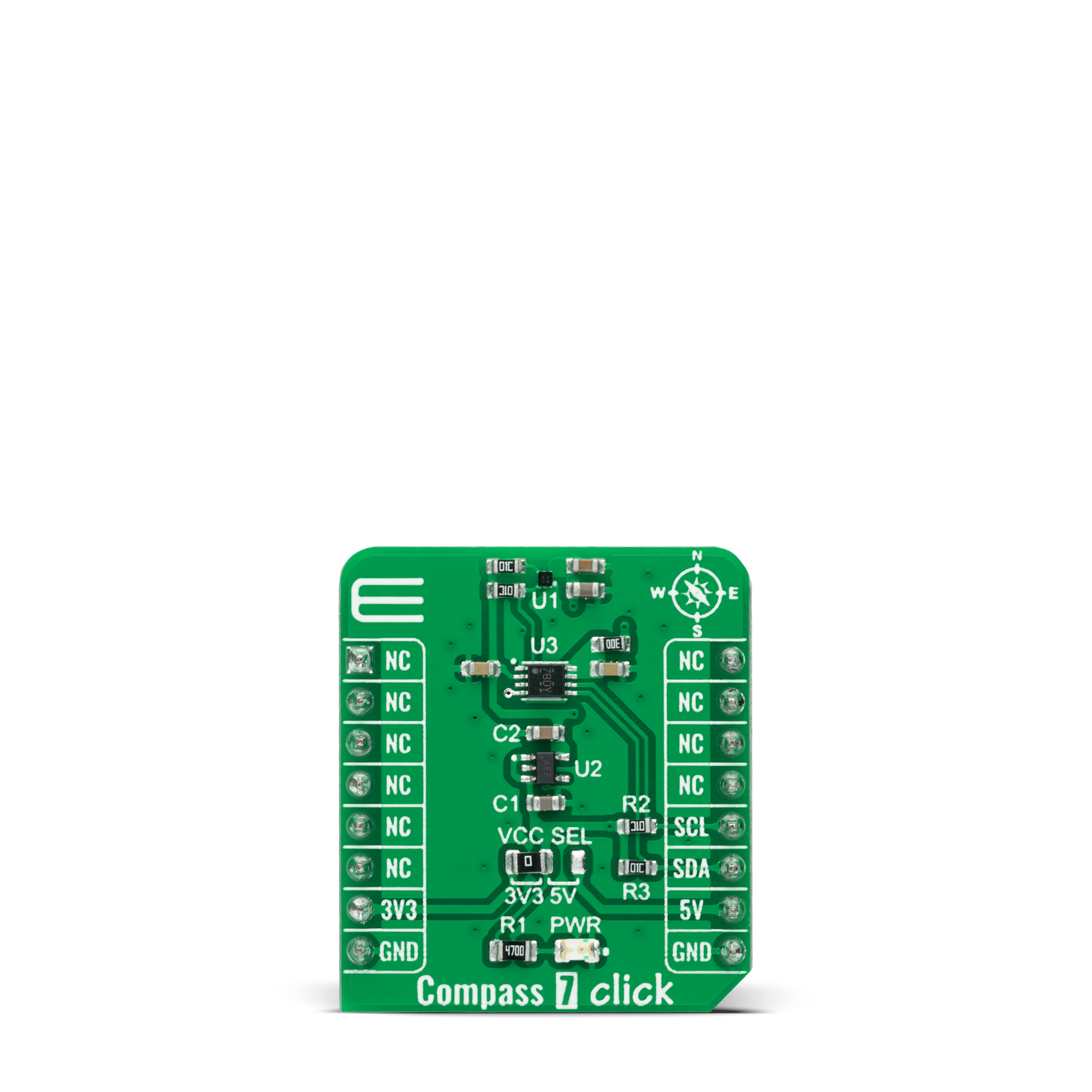
Compass 7 Click
Dev.Board
Fusion for PIC32 v8
Compiler
NECTO Studio
MCU
PIC32MZ2048EFH144
Detect the direction and magnitude of the external magnetic field accurately
A
A
Hardware Overview
How does it work?
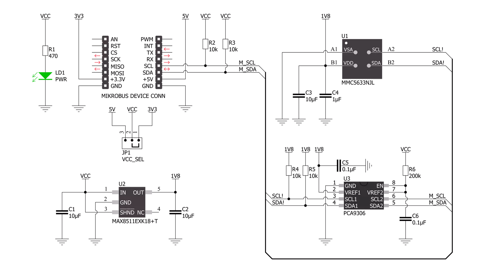
Compass 7 Click is based on the MMC5633NJL, a monolithic high-performance 3-axis AMR magnetic sensor from MEMSIC. It has an integrated drive circuit, signal processing circuit, and serial interface block, allowing low noise and high resolution. It can measure magnetic fields within the full-scale range of ±30 Gauss (G) with up to 0.0625mG per LSB resolution at 20bits operation mode and 2mG total RMS noise level, enabling heading accuracy of ±1º in electronic compass applications. An integrated SET/RESET function eliminates errors due to Null Field output change with temperature. In addition, it clears the sensors
of any residual magnetic polarization resulting from exposure to strong external magnets. The SET/RESET function can be performed periodically for each measurement as the specific application requires. Compass 7 Click communicates with MCU using the standard I2C 2-Wire interface with a maximum clock frequency of 400kHz, fully adjustable through software registers. The MMC5633NJL does not require a specific Power-Up sequence but requires a voltage of 1.8V for its interface and logic part to work correctly. Therefore, a small regulating LDO, the MAX8511, is used to provide a 1.8V out of mikroBUS™ power rails.
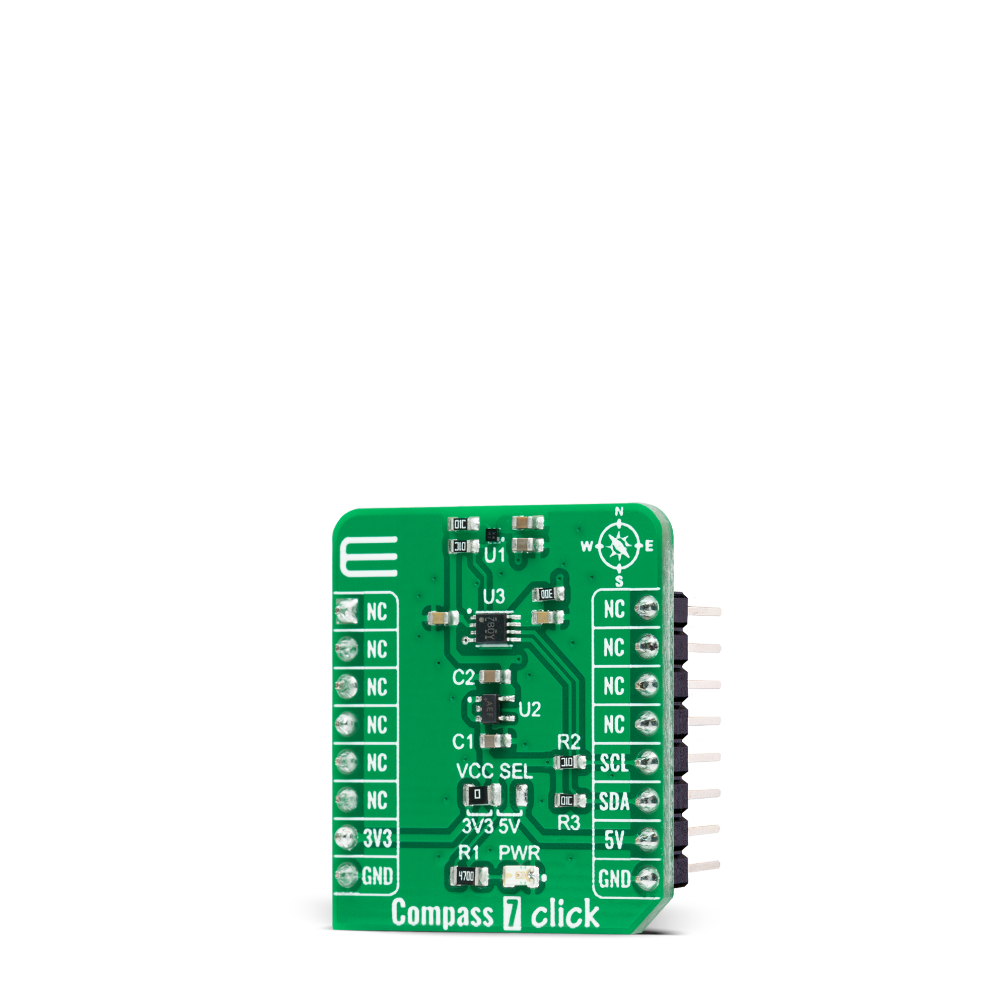
Since the sensor for operation requires a power supply of 1.8V, this Click board™ also features the PCA9306 voltage-level translator allowing the MMC5633NJL to work with 3.3V and 5V MCU properly. This Click board™ can operate with either 3.3V or 5V logic voltage levels selected via the VCC SEL jumper. This way, both 3.3V and 5V capable MCUs can use the communication lines properly. However, the Click board™ comes equipped with a library containing easy-to-use functions and an example code that can be used, as a reference, for further development.
Features overview
Development board
Fusion for PIC32 v8 is a development board specially designed for the needs of rapid development of embedded applications. It supports a wide range of Microchip's PIC32 microcontrollers regardless of their number of pins and a broad set of unique functions, such as the first-ever embedded debugger/programmer over WiFi. The development board is well organized and designed so that the end-user has all the necessary elements, such as switches, buttons, indicators, connectors, and others, in one place. Thanks to innovative manufacturing technology, Fusion for PIC32 v8 provides a fluid and immersive working experience, allowing access anywhere and under any circumstances at any time. Each part of the
Fusion for PIC32 v8 development board contains the components necessary for the most efficient operation of the same board. In addition to the advanced integrated CODEGRIP programmer/debugger module, which offers many valuable programming/debugging options and seamless integration with the Mikroe software environment, the board also includes a clean and regulated power supply module for the development board. It can use a wide range of external power sources, including a battery, an external 12V power supply, and a power source via the USB Type-C (USB-C) connector. Communication options such as USB-UART, USB HOST/DEVICE, CAN (on the MCU card, if
supported), and Ethernet is also included. In addition, it also has the well-established mikroBUS™ standard, a standardized socket for the MCU card (SiBRAIN standard), and two display options for the TFT board line of products and character-based LCD. Fusion for PIC32 v8 is an integral part of the Mikroe ecosystem for rapid development. Natively supported by Mikroe software tools, it covers many aspects of prototyping and development thanks to a considerable number of different Click boards™ (over a thousand boards), the number of which is growing every day.

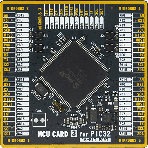
Microcontroller Overview
MCU Card / MCU
Type
8th Generation
Architecture
PIC32
MCU Memory (KB)
2048
Silicon Vendor
Microchip
Pin count
144
RAM (Bytes)
524288
Used MCU Pins
mikroBUS™ mapper
Take a closer look
Schematic
Step by step
Project assembly

Start by selecting your development board and Click board™. Begin with the Fusion for PIC32 v8 as your development board.


Track your results in real time
Application Output
After pressing the "FLASH" button on the left-side panel, it is necessary to open the UART terminal to display the achieved results. By clicking on the Tools icon in the right-hand panel, multiple different functions are displayed, among which is the UART Terminal. Click on the offered "UART Terminal" icon.

Once the UART terminal is opened, the window takes on a new form. At the top of the tab are two buttons, one for adjusting the parameters of the UART terminal and the other for connecting the UART terminal. The tab's lower part is reserved for displaying the achieved results. Before connecting, the terminal has a Disconnected status, indicating that the terminal is not yet active. Before connecting, it is necessary to check the set parameters of the UART terminal. Click on the "OPTIONS" button.

In the newly opened UART Terminal Options field, we check if the terminal settings are correct, such as the set port and the Baud rate of UART communication. If the data is not displayed properly, it is possible that the Baud rate value is not set correctly and needs to be adjusted to 115200. If all the parameters are set correctly, click on "CONFIGURE".

The next step is to click on the "CONNECT" button, after which the terminal status changes from Disconnected to Connected in green, and the data is displayed in the Received data field.

Software Support
Library Description
This library contains API for Compass 7 Click driver.
Key functions:
compass7_set_measurement_modeThis function sets the control and ODR registers for the selected measurement mode.compass7_get_magnetic_fluxThis function reads the raw values of X, Y, and Z axis and converts them to magnetic flux data in Gauss.compass7_get_temperatureThis function reads the temperature measurements in Celsius.
Open Source
Code example
This example can be found in NECTO Studio. Feel free to download the code, or you can copy the code below.
/*!
 * @file main.c
 * @brief Compass7 Click example
 *
 * # Description
 * This example demonstrates the use of Compass 7 click board by reading and displaying
 * the magnetic field strength of 3-axis as well as the temperature measurements in Celsius.
 *
 * The demo application is composed of two sections :
 *
 * ## Application Init
 * Initializes the driver and performs the click default configuration.
 *
 * ## Application Task
 * Starts the single magnetic measurement and reads the magnetic field strength of 3-axis in Gauss,
 * then starts the temperature measurement and reads the temperature in Celsius.
 * The results are being displayed on the USB UART every 100ms approximately.
 *
 * @author Stefan Filipovic
 *
 */

#include "board.h"
#include "log.h"
#include "compass7.h"

static compass7_t compass7;
static log_t logger;

void application_init ( void )
{
    log_cfg_t log_cfg;  /**< Logger config object. */
    compass7_cfg_t compass7_cfg;  /**< Click config object. */

    /**
     * Logger initialization.
     * Default baud rate: 115200
     * Default log level: LOG_LEVEL_DEBUG
     * @note If USB_UART_RX and USB_UART_TX
     * are defined as HAL_PIN_NC, you will
     * need to define them manually for log to work.
     * See @b LOG_MAP_USB_UART macro definition for detailed explanation.
     */
    LOG_MAP_USB_UART( log_cfg );
    log_init( &logger, &log_cfg );
    log_info( &logger, " Application Init " );

    // Click initialization.
    compass7_cfg_setup( &compass7_cfg );
    COMPASS7_MAP_MIKROBUS( compass7_cfg, MIKROBUS_1 );
    if ( I2C_MASTER_ERROR == compass7_init( &compass7, &compass7_cfg ) )
    {
        log_error( &logger, " Communication init." );
        for ( ; ; );
    }

    if ( COMPASS7_ERROR == compass7_default_cfg ( &compass7 ) )
    {
        log_error( &logger, " Default configuration." );
        for ( ; ; );
    }

    log_info( &logger, " Application Task " );
}

void application_task ( void )
{
    compass7_magnetic_flux_t magnetic_flux;
    float temperature;
    if ( ( COMPASS7_OK == compass7_set_measurement_mode ( &compass7, COMPASS7_MEAS_SINGLE_M ) ) &&
         ( COMPASS7_OK == compass7_get_magnetic_flux ( &compass7, &magnetic_flux ) ) )
    {
        log_printf ( &logger, " X: %.2f G\r\n", magnetic_flux.x_axis );
        log_printf ( &logger, " Y: %.2f G\r\n", magnetic_flux.y_axis );
        log_printf ( &logger, " Z: %.2f G\r\n", magnetic_flux.z_axis );
    }
    if ( ( COMPASS7_OK == compass7_set_measurement_mode ( &compass7, COMPASS7_MEAS_SINGLE_T ) ) &&
         ( COMPASS7_OK == compass7_get_temperature ( &compass7, &temperature ) ) )
    {
        log_printf ( &logger, " Temperature: %.2f C\r\n\n", temperature );
    }
    Delay_ms ( 100 );
}

void main ( void )
{
    application_init( );

    for ( ; ; )
    {
        application_task( );
    }
}

// ------------------------------------------------------------------------ END


