Explore the endless potential of proximity detection with TMD3719 and ATmega328P
Proximity sensing: Creating smarter and safer environments
Published Feb 14, 2024
Click board™
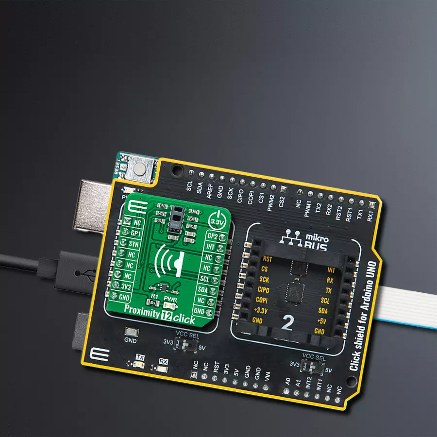
Proximity 12 Click
Dev. board
Arduino UNO Rev3
Compiler
NECTO Studio
MCU
ATmega328P
With proximity detection, we're unlocking the doors to a world where automation and personalization combine to enhance every moment
A
A
Hardware Overview
How does it work?
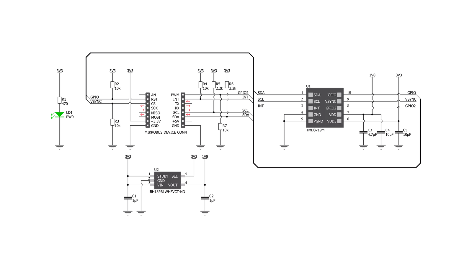
Proximity 12 Click is based on the TMD3719, an optical sensor that integrates ambient light sensing, proximity detection, and flicker detection sensing from ams OSRAM. The ambient light and color sensing function provide six concurrent ambient light sensing channels: Red, Green, Blue, Clear, Leakage, and Wideband, which accurately measure ambient light and calculate illuminance, chromaticity, and color temperature. The TMD3719 also integrates direct detection of ambient light flicker for four selectable frequency bins, executed parallel with ambient light and color sensing. The proximity function synchronizes IR emission and detection to sense nearby objects. This function features self-maximizing dynamic range, ambient light subtraction, and advanced cross-talk cancelation. The proximity engine recognizes
detect/release events and produces a configurable interrupt, routed to the INT pin of the mikroBUS™ socket, whenever the proximity result crosses upper or lower threshold settings. Proximity 12 Click communicates with MCU using the standard I2C 2-Wire interface with a maximum clock frequency of up to 400kHz. In addition to I2C communication, several GPIO pins connected to the mikroBUS™ socket pins are also used. The SYN pin, routed to the CS pin of the mikroBUS™ socket, is used to synchronize data and allows the start of the classic ambient light, proximity sensing, and flicker detection with every new SYN signal instead of immediately. It also has two pins labeled GP1 and GP2, routed on the RST and PWM pins of the mikroBUS™ socket, used as general-purpose pins, more precisely, GP1 as open-drain
general-purpose input/output and GP2 only as an input pin. The TMD3719 requires a supply voltage of 1.8V to work correctly. Therefore, a small regulating LDO, the BH18PB1WHFV from Rohm Semiconductor, provides a 1.8V out of 3.3V mikroBUS™ rail. The LDO cuts power consumption by lowering its current consumption to approximately 2μA when the application operates in the Standby state. This Click board™ can be operated only with a 3.3V logic voltage level. The board must perform appropriate logic voltage level conversion before using MCUs with different logic levels. Also, it comes equipped with a library containing functions and an example code that can be used as a reference for further development.


Features overview
Development board
Arduino UNO is a versatile microcontroller board built around the ATmega328P chip. It offers extensive connectivity options for various projects, featuring 14 digital input/output pins, six of which are PWM-capable, along with six analog inputs. Its core components include a 16MHz ceramic resonator, a USB connection, a power jack, an
ICSP header, and a reset button, providing everything necessary to power and program the board. The Uno is ready to go, whether connected to a computer via USB or powered by an AC-to-DC adapter or battery. As the first USB Arduino board, it serves as the benchmark for the Arduino platform, with "Uno" symbolizing its status as the
first in a series. This name choice, meaning "one" in Italian, commemorates the launch of Arduino Software (IDE) 1.0. Initially introduced alongside version 1.0 of the Arduino Software (IDE), the Uno has since become the foundational model for subsequent Arduino releases, embodying the platform's evolution.

Microcontroller Overview
MCU Card / MCU

Architecture
AVR
MCU Memory (KB)
32
Silicon Vendor
Microchip
Pin count
28
RAM (Bytes)
2048
You complete me!
Accessories
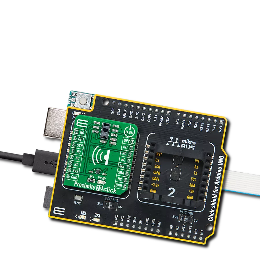
Click Shield for Arduino UNO has two proprietary mikroBUS™ sockets, allowing all the Click board™ devices to be interfaced with the Arduino UNO board without effort. The Arduino Uno, a microcontroller board based on the ATmega328P, provides an affordable and flexible way for users to try out new concepts and build prototypes with the ATmega328P microcontroller from various combinations of performance, power consumption, and features. The Arduino Uno has 14 digital input/output pins (of which six can be used as PWM outputs), six analog inputs, a 16 MHz ceramic resonator (CSTCE16M0V53-R0), a USB connection, a power jack, an ICSP header, and reset button. Most of the ATmega328P microcontroller pins are brought to the IO pins on the left and right edge of the board, which are then connected to two existing mikroBUS™ sockets. This Click Shield also has several switches that perform functions such as selecting the logic levels of analog signals on mikroBUS™ sockets and selecting logic voltage levels of the mikroBUS™ sockets themselves. Besides, the user is offered the possibility of using any Click board™ with the help of existing bidirectional level-shifting voltage translators, regardless of whether the Click board™ operates at a 3.3V or 5V logic voltage level. Once you connect the Arduino UNO board with our Click Shield for Arduino UNO, you can access hundreds of Click boards™, working with 3.3V or 5V logic voltage levels.

Used MCU Pins
mikroBUS™ mapper
Take a closer look
Click board™ Schematic
Step by step
Project assembly

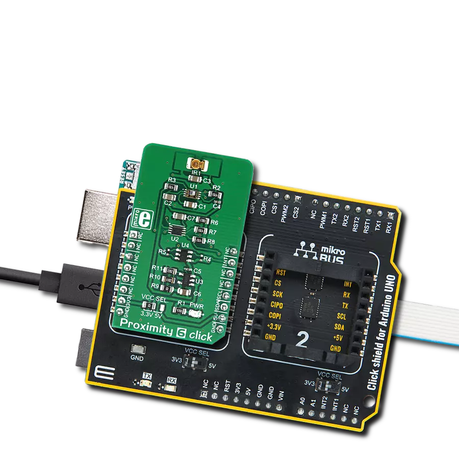
Start by selecting your development board and Click board™. Begin with the Arduino UNO Rev3 as your development board.


Track your results in real time
Application Output
1. Application Output - In Debug mode, the 'Application Output' window enables real-time data monitoring, offering direct insight into execution results. Ensure proper data display by configuring the environment correctly using the provided tutorial.

2. UART Terminal - Use the UART Terminal to monitor data transmission via a USB to UART converter, allowing direct communication between the Click board™ and your development system. Configure the baud rate and other serial settings according to your project's requirements to ensure proper functionality. For step-by-step setup instructions, refer to the provided tutorial.

3. Plot Output - The Plot feature offers a powerful way to visualize real-time sensor data, enabling trend analysis, debugging, and comparison of multiple data points. To set it up correctly, follow the provided tutorial, which includes a step-by-step example of using the Plot feature to display Click board™ readings. To use the Plot feature in your code, use the function: plot(*insert_graph_name*, variable_name);. This is a general format, and it is up to the user to replace 'insert_graph_name' with the actual graph name and 'variable_name' with the parameter to be displayed.

Software Support
Library Description
This library contains API for Proximity 12 Click driver.
Key functions:
proximity12_read_proximity- This function reads the raw proximity value measured by the click board.proximity12_read_als- This function reads all als data measured by the click board.proximity12_set_led_isink- This function sets the LEDs sink scaler and current values.
Open Source
Code example
The complete application code and a ready-to-use project are available through the NECTO Studio Package Manager for direct installation in the NECTO Studio. The application code can also be found on the MIKROE GitHub account.
/*!
 * @file main.c
 * @brief Proximity12 Click example
 *
 * # Description
 * This function demonstrates the use of Proximity 12 Click board.
 *
 * The demo application is composed of two sections :
 *
 * ## Application Init
 * Initializes the driver and performs the Click default configuration.
 *
 * ## Application Task
 * Reads the proximity and ALS values and displays the results on the USB UART
 * approximately every 100ms.
 *
 * @author Stefan Filipovic
 *
 */

#include "board.h"
#include "log.h"
#include "proximity12.h"

static proximity12_t proximity12;
static log_t logger;

void application_init ( void )
{
    log_cfg_t log_cfg;                  /**< Logger config object. */
    proximity12_cfg_t proximity12_cfg;  /**< Click config object. */

    /**
     * Logger initialization.
     * Default baud rate: 115200
     * Default log level: LOG_LEVEL_DEBUG
     * @note If USB_UART_RX and USB_UART_TX
     * are defined as HAL_PIN_NC, you will
     * need to define them manually for log to work.
     * See @b LOG_MAP_USB_UART macro definition for detailed explanation.
     */
    LOG_MAP_USB_UART( log_cfg );
    log_init( &logger, &log_cfg );
    Delay_ms ( 100 );
    log_info( &logger, " Application Init " );

    // Click initialization.
    proximity12_cfg_setup( &proximity12_cfg );
    PROXIMITY12_MAP_MIKROBUS( proximity12_cfg, MIKROBUS_1 );
    err_t init_flag = proximity12_init( &proximity12, &proximity12_cfg );
    if ( I2C_MASTER_ERROR == init_flag )
    {
        log_error( &logger, " Application Init Error. " );
        log_info( &logger, " Please, run program again... " );

        for ( ; ; );
    }
    Delay_ms ( 100 );

    init_flag = proximity12_default_cfg ( &proximity12 );
    if ( PROXIMITY12_ERROR == init_flag )
    {
        log_error( &logger, " Default Cfg Error. " );
        log_info( &logger, " Please, run program again... " );

        for ( ; ; );
    }
    log_info( &logger, " Application Task " );
}

void application_task ( void )
{
    uint16_t prox_data = 0;
    proximity12_als_data_t als;
    err_t error_flag = proximity12_read_proximity ( &proximity12, &prox_data );
    error_flag |= proximity12_read_als ( &proximity12, &als );

    if ( PROXIMITY12_OK == error_flag )
    {
        log_printf( &logger, " - Proximity data -\r\n" );
        log_printf( &logger, " Proximity: %u\r\n", prox_data );
        log_printf( &logger, " - ALS data -\r\n" );
        log_printf( &logger, " Clear: %lu - Red: %lu - Green: %lu - Blue: %lu\r\n", als.clear,
                                                                                    als.red,
                                                                                    als.green,
                                                                                    als.blue );

        log_printf( &logger, " Leakage: %lu - Wideband: %lu - IR1: %lu - IR2: %lu\r\n\r\n", als.leakage,
                                                                                            als.wideband,
                                                                                            als.ir1,
                                                                                            als.ir2 );
    }
    Delay_ms ( 100 );
}

int main ( void )
{
    /* Do not remove this line or clock might not be set correctly. */
    #ifdef PREINIT_SUPPORTED
    preinit();
    #endif

    application_init( );

    for ( ; ; )
    {
        application_task( );
    }

    return 0;
}

// ------------------------------------------------------------------------ END
Additional Support
Resources
Category:Proximity