Create contactless switches for applications where physical contact is impractical or undesirable with NMH1000 and ATmega2560
Hall-effect magnetic switch
Published Feb 14, 2024
Click board™
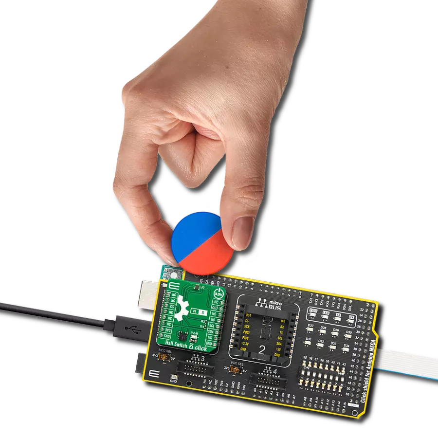
Hall Switch 3 Click
Dev. board
Arduino Mega 2560 Rev3
Compiler
NECTO Studio
MCU
ATmega2560
Detect changes in vertical magnetic fields and achieve unparalleled sensitivity to specific magnet orientations
A
A
Hardware Overview
How does it work?
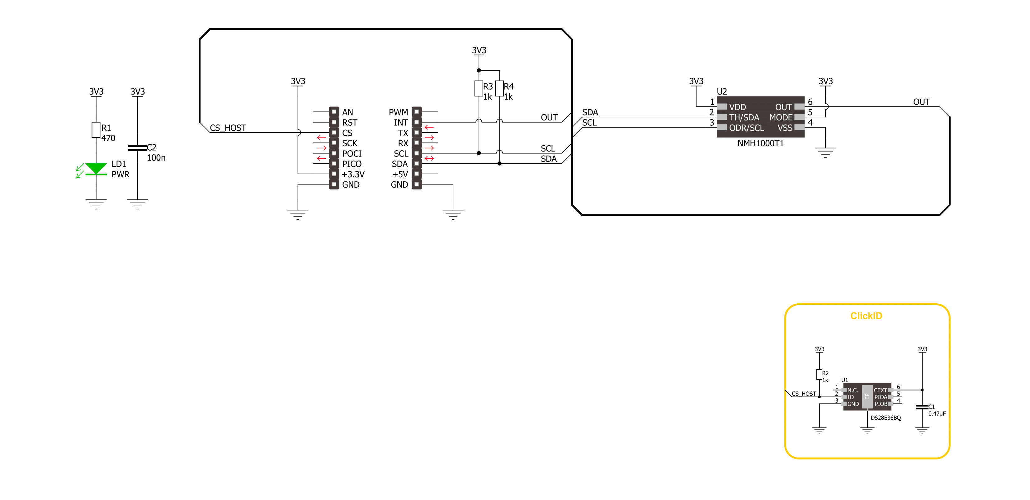
Hall Switch 3 Click is based on the NMH1000, a Hall-effect magnetic switch from NXP Semiconductor. The switch processes its input over the functional blocks that consist of a configurable state machine, an analog-to-voltage conversion of the input, and a comparison to generate the bi-state output. The output is arranged in a linear succession. The NMH1000 has a transducer that generates a small charge proportional to the
proximal magnetic flux density. The Hall-effect charge is converted to voltage and compared with the pre-defined threshold voltage. This determines the state of the switch's output. Hall Switch 3 Click uses a standard 2-wire I2C interface to communicate with the host MCU, supporting a clock frequency of up to 1MHz. The output of the switch, according to the pre-defined threshold, is available over the output OUT pin. This Click
board™ can be operated only with a 3.3V logic voltage level. The board must perform appropriate logic voltage level conversion before using MCUs with different logic levels. Also, it comes equipped with a library containing functions and an example code that can be used as a reference for further development.

Features overview
Development board
Arduino Mega 2560 is a robust microcontroller platform built around the ATmega 2560 chip. It has extensive capabilities and boasts 54 digital input/output pins, including 15 PWM outputs, 16 analog inputs, and 4 UARTs. With a 16MHz crystal
oscillator ensuring precise timing, it offers seamless connectivity via USB, a convenient power jack, an ICSP header, and a reset button. This all-inclusive board simplifies microcontroller projects; connect it to your computer via USB or power it up
using an AC-to-DC adapter or battery. Notably, the Mega 2560 maintains compatibility with a wide range of shields crafted for the Uno, Duemilanove, or Diecimila boards, ensuring versatility and ease of integration.

Microcontroller Overview
MCU Card / MCU

Architecture
AVR
MCU Memory (KB)
256
Silicon Vendor
Microchip
Pin count
100
RAM (Bytes)
8192
You complete me!
Accessories
Click Shield for Arduino Mega comes equipped with four mikroBUS™ sockets, with two in the form of a Shuttle connector, allowing all the Click board™ devices to be interfaced with the Arduino Mega board with no effort. Featuring an AVR 8-bit microcontroller with advanced RISC architecture, 54 digital I/O pins, and Arduino™ compatibility, the Arduino Mega board offers limitless possibilities for prototyping and creating diverse applications. This board is controlled and powered conveniently through a USB connection to program and debug the Arduino Mega board efficiently out of the box, with an additional USB cable connected to the USB B port on the board. Simplify your project development with the integrated ATmega16U2 programmer and unleash creativity using the extensive I/O options and expansion capabilities. There are eight switches, which you can use as inputs, and eight LEDs, which can be used as outputs of the MEGA2560. In addition, the shield features the MCP1501, a high-precision buffered voltage reference from Microchip. This reference is selected by default over the EXT REF jumper at the bottom of the board. You can choose an external one, as you would usually do with an Arduino Mega board. There is also a GND hook for testing purposes. Four additional LEDs are PWR, LED (standard pin D13), RX, and TX LEDs connected to UART1 (mikroBUS™ 1 socket). This Click Shield also has several switches that perform functions such as selecting the logic levels of analog signals on mikroBUS™ sockets and selecting logic voltage levels of the mikroBUS™ sockets themselves. Besides, the user is offered the possibility of using any Click board™ with the help of existing bidirectional level-shifting voltage translators, regardless of whether the Click board™ operates at a 3.3V or 5V logic voltage level. Once you connect the Arduino Mega board with Click Shield for Arduino Mega, you can access hundreds of Click boards™, working with 3.3V or 5V logic voltage levels.

Used MCU Pins
mikroBUS™ mapper
Take a closer look
Click board™ Schematic
Step by step
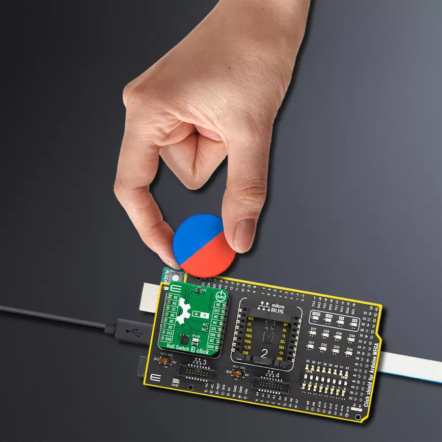
Project assembly

Start by selecting your development board and Click board™. Begin with the Arduino Mega 2560 Rev3 as your development board.


Track your results in real time
Application Output
1. Application Output - In Debug mode, the 'Application Output' window enables real-time data monitoring, offering direct insight into execution results. Ensure proper data display by configuring the environment correctly using the provided tutorial.

2. UART Terminal - Use the UART Terminal to monitor data transmission via a USB to UART converter, allowing direct communication between the Click board™ and your development system. Configure the baud rate and other serial settings according to your project's requirements to ensure proper functionality. For step-by-step setup instructions, refer to the provided tutorial.

3. Plot Output - The Plot feature offers a powerful way to visualize real-time sensor data, enabling trend analysis, debugging, and comparison of multiple data points. To set it up correctly, follow the provided tutorial, which includes a step-by-step example of using the Plot feature to display Click board™ readings. To use the Plot feature in your code, use the function: plot(*insert_graph_name*, variable_name);. This is a general format, and it is up to the user to replace 'insert_graph_name' with the actual graph name and 'variable_name' with the parameter to be displayed.

Software Support
Library Description
This library contains API for Hall Switch 3 Click Click driver.
Key functions:
hallswitch3_get_mag_data- This function is used to indicates a relative magnetic field strength.hallswitch3_set_out_data_rate- This function provides the capability for the user to override the fixed sample rate controlling the sleep-compare-Vout cycle time.hallswitch3_get_status- This function reads a status reporting of modes and selections.
Open Source
Code example
The complete application code and a ready-to-use project are available through the NECTO Studio Package Manager for direct installation in the NECTO Studio. The application code can also be found on the MIKROE GitHub account.
/*!
 * @file main.c
 * @brief Hall Switch 3 Click example
 *
 * # Description
 * This example demonstrates the use of Hall Switch 3 Click board
 * by reading and displaying the magnetic field strength value.
 *
 * The demo application is composed of two sections :
 *
 * ## Application Init
 * Initialization of I2C module and log UART.
 * After driver initialization, the app executes a default configuration.
 *
 * ## Application Task
 * This example demonstrates the use of the Hall Switch 3 Click board.
 * The demo application reads and displays the relative magnetic field strength value [Gaussian units]
 * and detects when the magnetic field strength is not in the configured range.
 * The results are sent to the UART terminal, where you can monitor their changes.
 *
 * @author Nenad Filipovic
 *
 */

#include "board.h"
#include "log.h"
#include "hallswitch3.h"

static hallswitch3_t hallswitch3;
static log_t logger;

void application_init ( void )
{
    log_cfg_t log_cfg;  /**< Logger config object. */
    hallswitch3_cfg_t hallswitch3_cfg;  /**< Click config object. */

    /**
     * Logger initialization.
     * Default baud rate: 115200
     * Default log level: LOG_LEVEL_DEBUG
     * @note If USB_UART_RX and USB_UART_TX
     * are defined as HAL_PIN_NC, you will
     * need to define them manually for log to work.
     * See @b LOG_MAP_USB_UART macro definition for detailed explanation.
     */
    LOG_MAP_USB_UART( log_cfg );
    log_init( &logger, &log_cfg );
    log_info( &logger, " Application Init " );

    // Click initialization.
    hallswitch3_cfg_setup( &hallswitch3_cfg );
    HALLSWITCH3_MAP_MIKROBUS( hallswitch3_cfg, MIKROBUS_1 );
    if ( I2C_MASTER_ERROR == hallswitch3_init( &hallswitch3, &hallswitch3_cfg ) )
    {
        log_error( &logger, " Communication init." );
        for ( ; ; );
    }

    if ( HALLSWITCH3_ERROR == hallswitch3_default_cfg ( &hallswitch3 ) )
    {
        log_error( &logger, " Default configuration." );
        for ( ; ; );
    }

    log_info( &logger, " Application Task " );
}

void application_task ( void )
{
    int8_t mag_data = 0;
    if ( HALLSWITCH3_OK == hallswitch3_get_mag_data( &hallswitch3, &mag_data ) )
    {
        log_printf( &logger, " Magnetic Field: %d [Gs]\r\n", ( int16_t ) mag_data );
        if ( HALLSWITCH3_OUT_STATE_LOW == hallswitch3_check_mag_field( &hallswitch3 ) )
        {
            log_printf( &logger, " The switch is open.\r\n" );
        }
    }
    Delay_ms ( 1000 );
}

int main ( void )
{
    /* Do not remove this line or clock might not be set correctly. */
    #ifdef PREINIT_SUPPORTED
    preinit();
    #endif

    application_init( );

    for ( ; ; )
    {
        application_task( );
    }

    return 0;
}

// ------------------------------------------------------------------------ END
Additional Support
Resources
Category:Magnetic


