Experience unparalleled angle detection with MA735 and ATmega2560
Magnet's whisper: Revealing angles in style!
Published Feb 14, 2024
Click board™
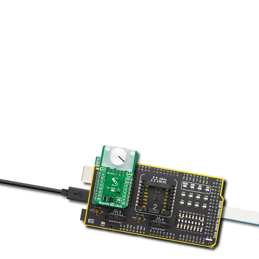
Magneto 14 Click
Dev. board
Arduino Mega 2560 Rev3
Compiler
NECTO Studio
MCU
ATmega2560
Your quest for precise angle information ends here – our solution, powered by magnetic insight, is your go-to tool for obtaining accurate and instantaneous measurements in any environment.
A
A
Hardware Overview
How does it work?
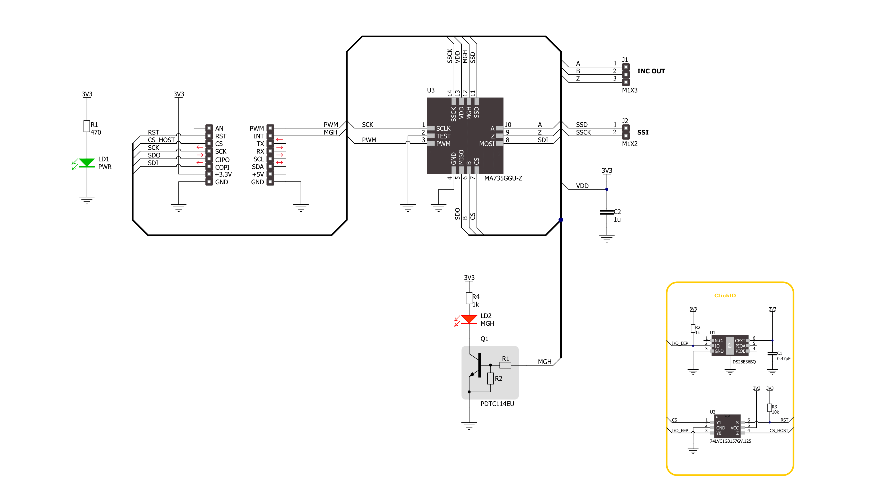
Magneto 14 Click is based on the MA735, a contactless angle sensor with ABZ and PWM output from Monolithic Power Systems. It can detect the absolute angular position of a permanent magnet, typically a diametrically magnetized cylinder on a rotating shaft. The adjustable digital filtering can optimize control loop performance when used in servo applications. In addition, the sensor features magnetic field strength detection with a programmable threshold and on-chip non-volatile memory. This memory can store configuration parameters, including magnetic field detection thresholds, ABZ encoder settings, and reference zero-angle positions. The frequency of the PWM output of the sensor is up to 1090Hz with a 14-bit resolution. The MA735 uses integrated Hall devices to detect the magnetic field, while the angle is measured using MPS’s proprietary Spinaxis™
method. This method is based on phase detection and digitizes the direction of the field directly, generating a sinusoidal signal with a phase that represents the angle of the field. The angle is obtained from a signal by a time-to-digital converter, and the digital number proportional to the magnetic field is delivered at a rate of 1MHz. Two headers on this Click board™ allow additional functionalities. The SSI header with SSD and SCK pins is a 2-wire synchronous serial interface for data reading only and can be used for angle reading operation. The INC OUT header is an incremental output encoder with A, B, and Z pins. The ABZ encoder emulates a 12-bit incremental encoder (like an optical encoder), providing logic pulses per turn from 1 to 1024 in quadrature. A unique addition to this board is a position for a Rotary Magnet Holder designed to be used alongside a magnetic contactless angle sensor,
allowing fast prototyping and quick measurements during development. The Magneto 14 Click uses a standard 4-Wire SPI serial interface with a maximum supported clock rate of 25MHz. The PWM absolute output provides a logic signal with a duty cycle proportional to the angle of the magnetic field on the pin PWM of the mikroBUS™ socket. This sensor has two thresholds, MGL and MGH, for low and high magnetic fields. The magnetic field high threshold (MFHT) is indicated over the MGH interrupt pin, together with an additional MGH red LED. This Click board™ can be operated only with a 3.3V logic voltage level. The board must perform appropriate logic voltage level conversion before using MCUs with different logic levels. Also, it comes equipped with a library containing functions and an example code that can be used as a reference for further development.

Features overview
Development board
Arduino Mega 2560 is a robust microcontroller platform built around the ATmega 2560 chip. It has extensive capabilities and boasts 54 digital input/output pins, including 15 PWM outputs, 16 analog inputs, and 4 UARTs. With a 16MHz crystal
oscillator ensuring precise timing, it offers seamless connectivity via USB, a convenient power jack, an ICSP header, and a reset button. This all-inclusive board simplifies microcontroller projects; connect it to your computer via USB or power it up
using an AC-to-DC adapter or battery. Notably, the Mega 2560 maintains compatibility with a wide range of shields crafted for the Uno, Duemilanove, or Diecimila boards, ensuring versatility and ease of integration.

Microcontroller Overview
MCU Card / MCU

Architecture
AVR
MCU Memory (KB)
256
Silicon Vendor
Microchip
Pin count
100
RAM (Bytes)
8192
You complete me!
Accessories
Click Shield for Arduino Mega comes equipped with four mikroBUS™ sockets, with two in the form of a Shuttle connector, allowing all the Click board™ devices to be interfaced with the Arduino Mega board with no effort. Featuring an AVR 8-bit microcontroller with advanced RISC architecture, 54 digital I/O pins, and Arduino™ compatibility, the Arduino Mega board offers limitless possibilities for prototyping and creating diverse applications. This board is controlled and powered conveniently through a USB connection to program and debug the Arduino Mega board efficiently out of the box, with an additional USB cable connected to the USB B port on the board. Simplify your project development with the integrated ATmega16U2 programmer and unleash creativity using the extensive I/O options and expansion capabilities. There are eight switches, which you can use as inputs, and eight LEDs, which can be used as outputs of the MEGA2560. In addition, the shield features the MCP1501, a high-precision buffered voltage reference from Microchip. This reference is selected by default over the EXT REF jumper at the bottom of the board. You can choose an external one, as you would usually do with an Arduino Mega board. There is also a GND hook for testing purposes. Four additional LEDs are PWR, LED (standard pin D13), RX, and TX LEDs connected to UART1 (mikroBUS™ 1 socket). This Click Shield also has several switches that perform functions such as selecting the logic levels of analog signals on mikroBUS™ sockets and selecting logic voltage levels of the mikroBUS™ sockets themselves. Besides, the user is offered the possibility of using any Click board™ with the help of existing bidirectional level-shifting voltage translators, regardless of whether the Click board™ operates at a 3.3V or 5V logic voltage level. Once you connect the Arduino Mega board with Click Shield for Arduino Mega, you can access hundreds of Click boards™, working with 3.3V or 5V logic voltage levels.

Rotary Magnetic Holder is an addition designed for use alongside a magnetic rotary position sensor. It comes with a plastic stand measuring 22x16x10 millimeters (L x W x H), as well as an adjustable shaft with a 6mm diameter magnet. The plastic frame has four round feet that fit into holes in the board near the magnetic rotary position sensor, with a 6mm diameter hole on top to match the adjustable shaft that carries the magnet. This shaft has a height adjustment screw on it, allowing the user to adjust it between 18 and 22 millimeters. This way, fast prototyping and quick measurements of the magnet characteristics are allowed during development.

Used MCU Pins
mikroBUS™ mapper
Take a closer look
Click board™ Schematic
Step by step
Project assembly

Start by selecting your development board and Click board™. Begin with the Arduino Mega 2560 Rev3 as your development board.


Software Support
Library Description
This library contains API for Magneto 14 Click driver.
Key functions:
magneto14_get_angle- Magneto 14 gets the angular position function.magneto14_get_field_strength- Magneto 14 gets the magnetic field strength function.magneto14_get_mgh- Magneto 14 gets the MGH function.
Open Source
Code example
The complete application code and a ready-to-use project are available through the NECTO Studio Package Manager for direct installation in the NECTO Studio. The application code can also be found on the MIKROE GitHub account.
/*!
 * @file main.c
 * @brief Magneto 14 Click example
 *
 * # Description
 * This library contains API for the Magneto 14 Click driver.
 * The demo application reads and displays
 * the magnet's angular position in degrees.
 *
 * The demo application is composed of two sections :
 *
 * ## Application Init
 * Initialization of SPI module and log UART.
 * After driver initialization, the app executes a default configuration.
 *
 * ## Application Task
 * This example demonstrates the use of the Magneto 14 Click board™.
 * Reads and displays the magnet's angular position in degrees.
 * Results are being sent to the UART Terminal, where you can track their changes.
 *
 * @author Nenad Filipovic
 *
 */

#include "board.h"
#include "log.h"
#include "magneto14.h"

static magneto14_t magneto14;
static log_t logger;

void application_init ( void )
{
    log_cfg_t log_cfg;  /**< Logger config object. */
    magneto14_cfg_t magneto14_cfg;  /**< Click config object. */

    /**
     * Logger initialization.
     * Default baud rate: 115200
     * Default log level: LOG_LEVEL_DEBUG
     * @note If USB_UART_RX and USB_UART_TX
     * are defined as HAL_PIN_NC, you will
     * need to define them manually for log to work.
     * See @b LOG_MAP_USB_UART macro definition for detailed explanation.
     */
    LOG_MAP_USB_UART( log_cfg );
    log_init( &logger, &log_cfg );
    log_info( &logger, " Application Init " );

    // Click initialization.
    magneto14_cfg_setup( &magneto14_cfg );
    MAGNETO14_MAP_MIKROBUS( magneto14_cfg, MIKROBUS_1 );
    if ( SPI_MASTER_ERROR == magneto14_init( &magneto14, &magneto14_cfg ) )
    {
        log_error( &logger, " Communication init." );
        for ( ; ; );
    }

    if ( MAGNETO14_ERROR == magneto14_default_cfg ( &magneto14 ) )
    {
        log_error( &logger, " Default configuration." );
        for ( ; ; );
    }

    log_info( &logger, " Application Task " );
    log_printf( &logger, " -------------------- \r\n" );
    Delay_ms ( 100 );
}

void application_task ( void )
{
    static uint8_t field_strength = 0;
    static float angle = 0;
    if ( MAGNETO14_OK == magneto14_get_field_strength( &magneto14, &field_strength ) )
    {
        if ( ( MAGNETO14_FLD_ST_OK == field_strength ) &&
             ( MAGNETO14_MGH_ST_OK == magneto14_get_mgh( &magneto14 ) ) &&
             ( MAGNETO14_OK == magneto14_get_angle( &magneto14, &angle ) ) )
        {
            log_printf( &logger, " Angle: %.2f [deg]\r\n", angle );
            log_printf( &logger, " -------------------- \r\n" );
            Delay_ms ( 1000 );
        }
    }
}

int main ( void )
{
    /* Do not remove this line or clock might not be set correctly. */
    #ifdef PREINIT_SUPPORTED
    preinit();
    #endif

    application_init( );

    for ( ; ; )
    {
        application_task( );
    }

    return 0;
}

// ------------------------------------------------------------------------ END
Additional Support
Resources
Category:Magnetic


