Ensure flawless detection of absolute angular magnet positions with MA736 and STM32F413ZH
Seamless spin, impeccable precision
Published Feb 14, 2024
Click board™
Magneto 13 Click
Dev. board
Nucleo 144 with STM32F413ZH MCU
Compiler
NECTO Studio
MCU
STM32F413ZH
Revolutionize your machinery with our solution that accurately detects the absolute angular position of any diametrically magnetized cylinder or rotating shaft.
A
A
Hardware Overview
How does it work?
Magneto 13 Click is based on the MA736, a contactless digital angle sensor from Monolithic Power Systems. Its angle encoder has a configurable 8-bit to 12.5-bit absolute resolution and low latency at a constant rotation speed, allowing rotation measurements from 0 to 60.000 RPM. If used in servo motor applications, it is worth knowing that digital filtering is adjustable to optimize the control loop performance. For the best performance, the best mounting method would be to place the sensor on the rotation axis of a permanent magnet, such as a diametrically magnetized cylinder. The Magneto 13 Click detects the strength of the magnetic field, and for diagnostic purposes, it uses configurable thresholds. The configuration parameters, such as the reference zero-angle and magnetic field
detection threshold, are stored in on-chip non-volatile memory (NVM). The values from the NVM are loaded automatically during the Start-up condition and can be restored through the SPI interface. The sensor detects the magnetic field with the integrated Hall devices, with the angle measured with the SpinAxis method, which digitizes the direction of the field. Doing so, it does not need feedback loop-based circuits or complex arctangent computations. This method generates a sinusoidal signal with a phase representing the magnetic field's angle. The angle is obtained by a time-to-digital converter that measures the time between the zero crossing of the sinusoidal signal and the edge of a constant waveform. To communicate with the host MCU, this Click board™ uses the standard 4-Wire SPI serial
interface, supporting SPI mode 0 and mode 3. Modes are detected automatically by the sensor. In addition, error flags with active HIGH are available on the ERR pin. The angle changes exceeding the defined threshold are indicated as output interruptions over the IRQ pin. The NVM pin is the output that MA736 uses to indicate whether it is busy accessing the non-volatile memory. Also, two LEDs, MGH and MGL, make a visual presentation if the field strength is above or below the selected threshold. This Click board™ can be operated only with a 3.3V logic voltage level. The board must perform appropriate logic voltage level conversion before using MCUs with different logic levels. Also, it comes equipped with a library containing functions and an example code that can be used for further development.

Features overview
Development board
Nucleo-144 with STM32F413ZH MCU board offers an accessible and adaptable avenue for users to explore new ideas and construct prototypes. It allows users to tailor their experience by selecting from a range of performance and power consumption features offered by the STM32 microcontroller. With compatible boards, the
internal or external SMPS dramatically decreases power usage in Run mode. Including the ST Zio connector, expanding ARDUINO Uno V3 connectivity, and ST morpho headers facilitate easy expansion of the Nucleo open development platform. The integrated ST-LINK debugger/programmer enhances convenience by
eliminating the need for a separate probe. Moreover, the board is accompanied by comprehensive free software libraries and examples within the STM32Cube MCU Package, further enhancing its utility and value.

Microcontroller Overview
MCU Card / MCU

Architecture
ARM Cortex-M4
MCU Memory (KB)
1536
Silicon Vendor
STMicroelectronics
Pin count
144
RAM (Bytes)
327680
You complete me!
Accessories
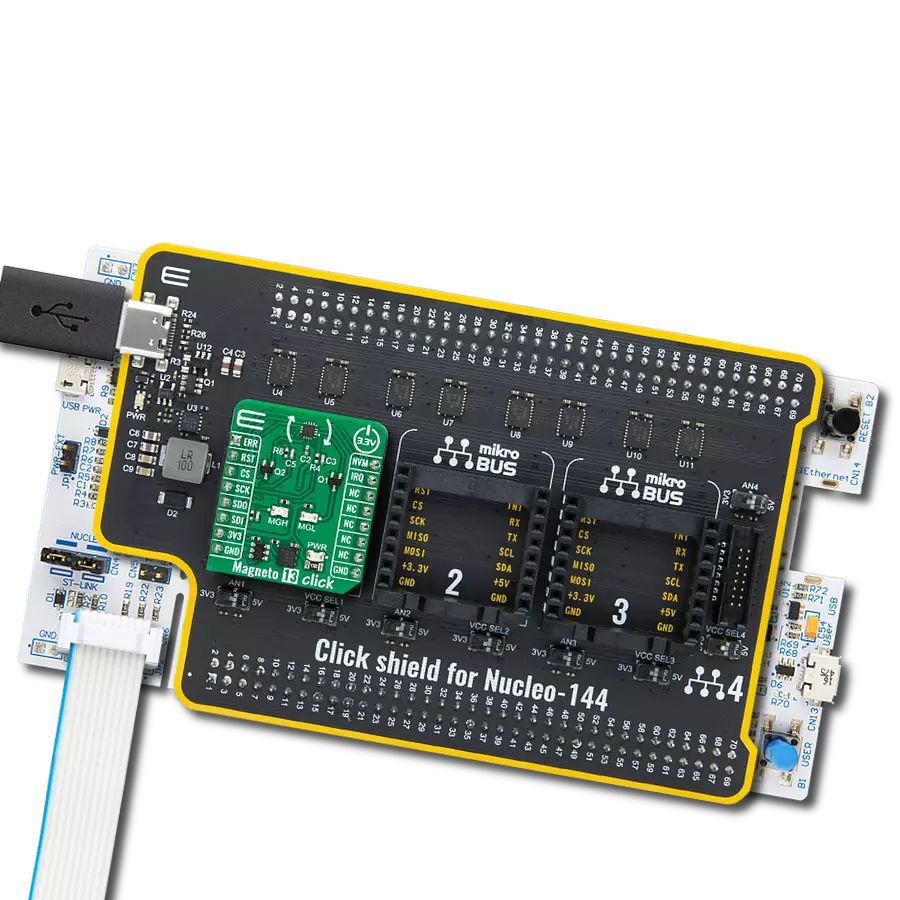
Click Shield for Nucleo-144 comes equipped with four mikroBUS™ sockets, with one in the form of a Shuttle connector, allowing all the Click board™ devices to be interfaced with the STM32 Nucleo-144 board with no effort. This way, MIKROE allows its users to add any functionality from our ever-growing range of Click boards™, such as WiFi, GSM, GPS, Bluetooth, ZigBee, environmental sensors, LEDs, speech recognition, motor control, movement sensors, and many more. Featuring an ARM Cortex-M microcontroller, 144 pins, and Arduino™ compatibility, the STM32 Nucleo-144 board offers limitless possibilities for prototyping and creating diverse applications. These boards are controlled and powered conveniently through a USB connection to program and efficiently debug the Nucleo-144 board out of the box, with an additional USB cable connected to the USB mini port on the board. Simplify your project development with the integrated ST-Link debugger and unleash creativity using the extensive I/O options and expansion capabilities. This Click Shield also has several switches that perform functions such as selecting the logic levels of analog signals on mikroBUS™ sockets and selecting logic voltage levels of the mikroBUS™ sockets themselves. Besides, the user is offered the possibility of using any Click board™ with the help of existing bidirectional level-shifting voltage translators, regardless of whether the Click board™ operates at a 3.3V or 5V logic voltage level. Once you connect the STM32 Nucleo-144 board with our Click Shield for Nucleo-144, you can access hundreds of Click boards™, working with 3.3V or 5V logic voltage levels.

Used MCU Pins
mikroBUS™ mapper
Take a closer look
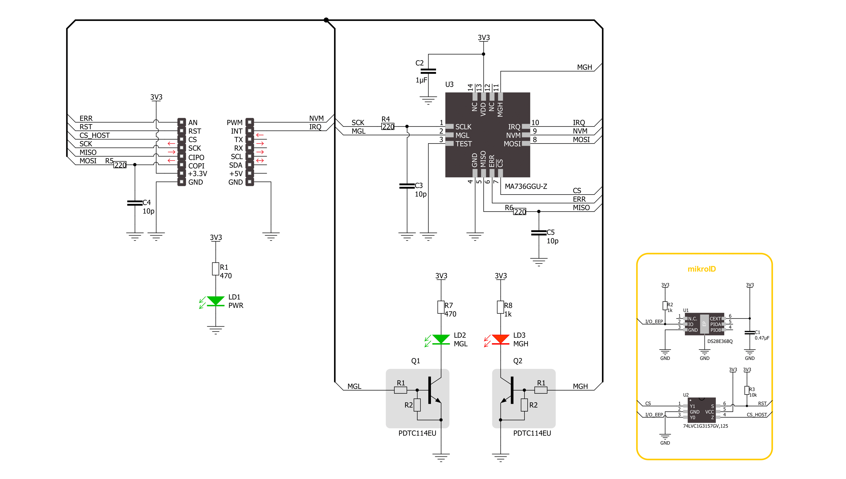
Click board™ Schematic
Step by step
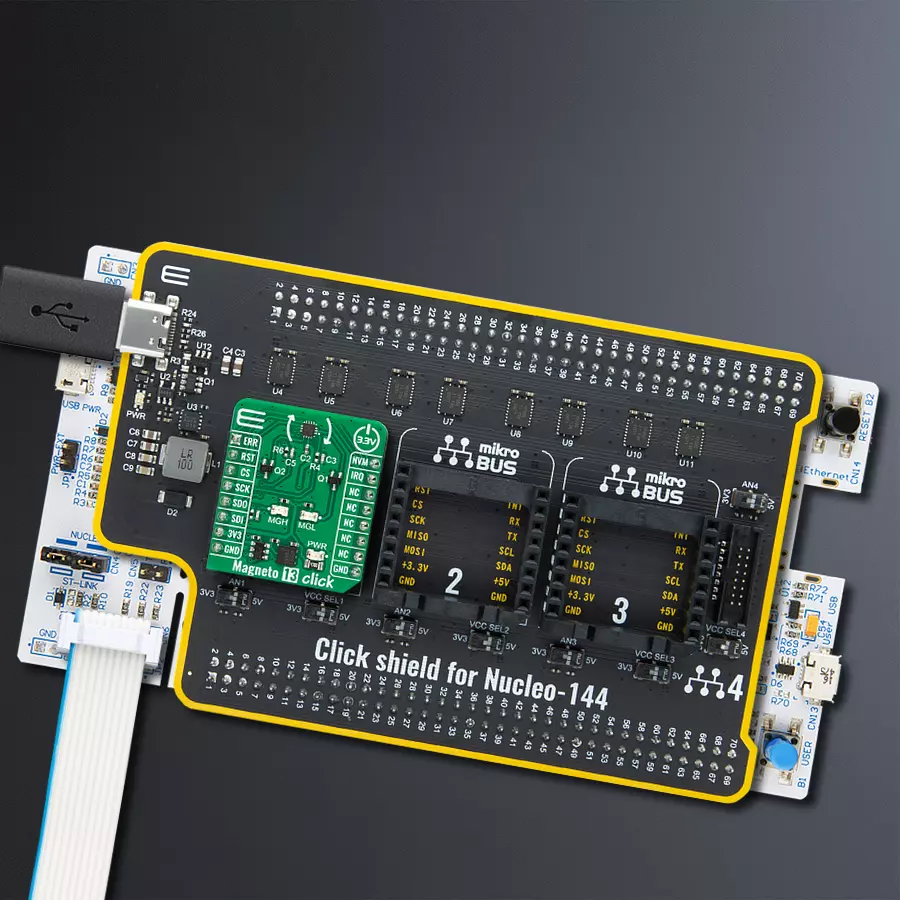
Project assembly
Start by selecting your development board and Click board™. Begin with the Nucleo 144 with STM32F413ZH MCU as your development board.


Software Support
Library Description
This library contains API for Magneto 13 Click driver.
Key functions:
magneto13_get_angle- Magneto 13 gets the angular position function.magneto13_get_field_strength- Magneto 13 gets the magnetic field strength function.magneto13_set_mag_field_thd- Magneto 13 sets the magnetic field threshold function.
Open Source
Code example
The complete application code and a ready-to-use project are available through the NECTO Studio Package Manager for direct installation in the NECTO Studio. The application code can also be found on the MIKROE GitHub account.
/*!
 * @file main.c
 * @brief Magneto 13 Click example
 *
 * # Description
 * This library contains API for the Magneto 13 Click driver.
 * The demo application reads and displays
 * the magnet's angular position in degrees.
 *
 * The demo application is composed of two sections :
 *
 * ## Application Init
 * Initialization of SPI module and log UART.
 * After driver initialization, the app executes a default configuration.
 *
 * ## Application Task
 * This example demonstrates the use of the Magneto 13 Click board™.
 * Reads and displays the magnet's angular position in degrees.
 * Results are being sent to the UART Terminal, where you can track their changes.
 *
 * @author Nenad Filipovic
 *
 */

#include "board.h"
#include "log.h"
#include "magneto13.h"

static magneto13_t magneto13;
static log_t logger;

void application_init ( void )
{
    log_cfg_t log_cfg;  /**< Logger config object. */
    magneto13_cfg_t magneto13_cfg;  /**< Click config object. */

    /**
     * Logger initialization.
     * Default baud rate: 115200
     * Default log level: LOG_LEVEL_DEBUG
     * @note If USB_UART_RX and USB_UART_TX
     * are defined as HAL_PIN_NC, you will
     * need to define them manually for log to work.
     * See @b LOG_MAP_USB_UART macro definition for detailed explanation.
     */
    LOG_MAP_USB_UART( log_cfg );
    log_init( &logger, &log_cfg );
    log_info( &logger, " Application Init " );

    // Click initialization.
    magneto13_cfg_setup( &magneto13_cfg );
    MAGNETO13_MAP_MIKROBUS( magneto13_cfg, MIKROBUS_1 );
    if ( SPI_MASTER_ERROR == magneto13_init( &magneto13, &magneto13_cfg ) )
    {
        log_error( &logger, " Communication init." );
        for ( ; ; );
    }

    if ( MAGNETO13_ERROR == magneto13_default_cfg ( &magneto13 ) )
    {
        log_error( &logger, " Default configuration." );
        for ( ; ; );
    }

    log_info( &logger, " Application Task " );
    log_printf( &logger, " -------------------- \r\n" );
    Delay_ms ( 100 );
}

void application_task ( void )
{
    static uint8_t field_strength = 0;
    static float angle = 0;
    if ( MAGNETO13_OK == magneto13_get_field_strength( &magneto13, &field_strength ) )
    {
        if ( ( MAGNETO13_FLD_ST_OK == field_strength ) && ( MAGNETO13_OK == magneto13_get_angle( &magneto13, &angle ) ) )
        {
            log_printf( &logger, " Angle: %.2f [deg]\r\n", angle );
            log_printf( &logger, " -------------------- \r\n" );
            Delay_ms ( 1000 );
        }
    }
}

int main ( void )
{
    /* Do not remove this line or clock might not be set correctly. */
    #ifdef PREINIT_SUPPORTED
    preinit();
    #endif

    application_init( );

    for ( ; ; )
    {
        application_task( );
    }

    return 0;
}

// ------------------------------------------------------------------------ END
Additional Support
Resources
Category:Magnetic


