Illuminate, animate, and inspire with WS2812 and STM32F091RC
Pixels awaken!
Published Feb 26, 2024
Click board™
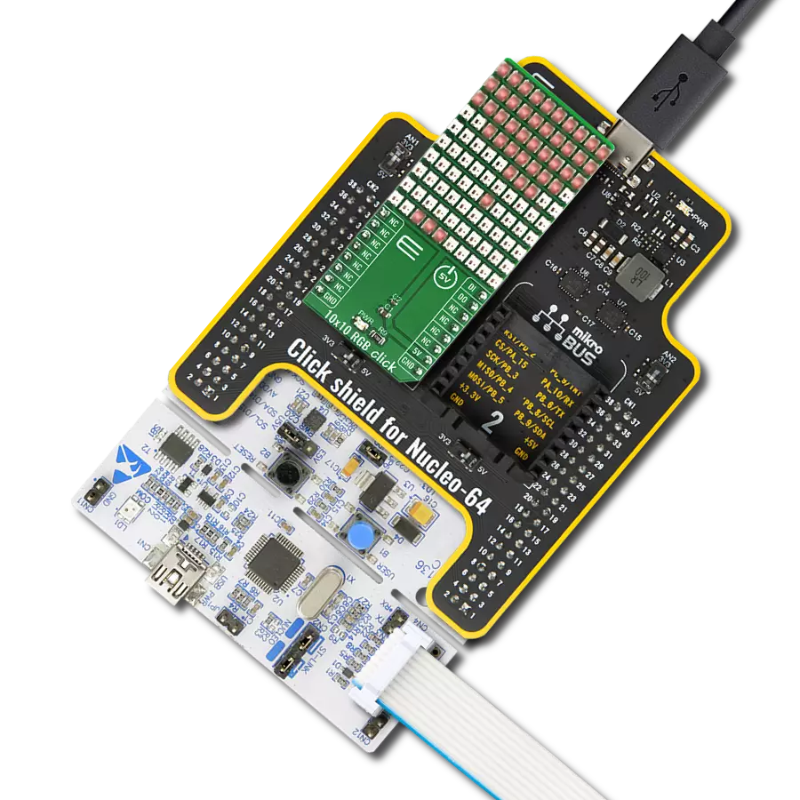
10x10 RGB Click
Dev. board
Nucleo-64 with STM32F091RC MCU
Compiler
NECTO Studio
MCU
STM32F091RC
Our solution, featuring a 10x10 display matrix of 100 'intelligent' RGB elements, transforms your creative ideas into mesmerizing visuals, making it the ultimate choice for dynamic displays, animations, and interactive presentations
A
A
Hardware Overview
How does it work?
10x10 RGB Click is based on the WS2812, an intelligent control LED light source from Worldsemi. Its exterior adopts the latest MOLDING packaging technology, and the control circuit and RGB chips are integrated into a package of 2020 components. It's internal includes an intelligent digital port data latch and signal reshaping amplification drive circuit. It also includes a precision internal oscillator and a voltage-programmable constant current control part, ensuring consistent pixel point light color height. The data transfer protocol use single NZR communication mode. After the pixel power-on reset, the DIN port receive data from controller, the first pixel collect initial 24bit data then sent to the internal data latch, the other data which reshaping by the internal signal reshaping amplification circuit sent to the next cascade pixel through the DO port. After transmission for each
pixel, the signal to reduce 24bit. pixel adopt auto reshaping transmit technology, making the pixel cascade number is not limited the signal transmission, only depend on the speed of signal transmission. RESET time >280μs , it won't cause wrong reset while interruption, it supports the lower frequency and inexpensive MCU. Refresh Frequency updates to 2KHz, Low Frame Frequency and No Flicker appear in HD Video Camera, it improve excellent display effect. LED with low driving voltage, environmental protection and energy saving, high brightness, large scattering angle, good consistency, low power, long life and other advantages. The control chip integrated in LED above becoming more simple circuit, small volume, convenient installation. 10x10 RGB Click can be used in many applications, like full-color module, full color soft lights a lamp strip, LED decorative lighting, indoor/outdoor LED
irregular screen, game machine and amusement equipment, and more. The INT pin of the mikroBUS™, which is labeled as DO on this Click board™, allows cascading of multiple 10x10 RGB click devices. It simply routes the data line back to the mikroBUS™, allowing it to be re-used for the next 10x10 RGB click, and so on. The length of the whole chain is limited only by the communication speed, required to scan through all the LED devices, in order to maintain a reasonable refresh speed. This Click board™ can be operated only with a 3.3V logic voltage level. The board must perform appropriate logic voltage level conversion before using MCUs with different logic levels. Also, it comes equipped with a library containing functions and an example code that can be used as a reference for further development.


Features overview
Development board
Nucleo-64 with STM32F091RC MCU offers a cost-effective and adaptable platform for developers to explore new ideas and prototype their designs. This board harnesses the versatility of the STM32 microcontroller, enabling users to select the optimal balance of performance and power consumption for their projects. It accommodates the STM32 microcontroller in the LQFP64 package and includes essential components such as a user LED, which doubles as an ARDUINO® signal, alongside user and reset push-buttons, and a 32.768kHz crystal oscillator for precise timing operations. Designed with expansion and flexibility in mind, the Nucleo-64 board features an ARDUINO® Uno V3 expansion connector and ST morpho extension pin
headers, granting complete access to the STM32's I/Os for comprehensive project integration. Power supply options are adaptable, supporting ST-LINK USB VBUS or external power sources, ensuring adaptability in various development environments. The board also has an on-board ST-LINK debugger/programmer with USB re-enumeration capability, simplifying the programming and debugging process. Moreover, the board is designed to simplify advanced development with its external SMPS for efficient Vcore logic supply, support for USB Device full speed or USB SNK/UFP full speed, and built-in cryptographic features, enhancing both the power efficiency and security of projects. Additional connectivity is
provided through dedicated connectors for external SMPS experimentation, a USB connector for the ST-LINK, and a MIPI® debug connector, expanding the possibilities for hardware interfacing and experimentation. Developers will find extensive support through comprehensive free software libraries and examples, courtesy of the STM32Cube MCU Package. This, combined with compatibility with a wide array of Integrated Development Environments (IDEs), including IAR Embedded Workbench®, MDK-ARM, and STM32CubeIDE, ensures a smooth and efficient development experience, allowing users to fully leverage the capabilities of the Nucleo-64 board in their projects.

Microcontroller Overview
MCU Card / MCU

Architecture
ARM Cortex-M0
MCU Memory (KB)
256
Silicon Vendor
STMicroelectronics
Pin count
64
RAM (Bytes)
32768
You complete me!
Accessories
Click Shield for Nucleo-64 comes equipped with two proprietary mikroBUS™ sockets, allowing all the Click board™ devices to be interfaced with the STM32 Nucleo-64 board with no effort. This way, Mikroe allows its users to add any functionality from our ever-growing range of Click boards™, such as WiFi, GSM, GPS, Bluetooth, ZigBee, environmental sensors, LEDs, speech recognition, motor control, movement sensors, and many more. More than 1537 Click boards™, which can be stacked and integrated, are at your disposal. The STM32 Nucleo-64 boards are based on the microcontrollers in 64-pin packages, a 32-bit MCU with an ARM Cortex M4 processor operating at 84MHz, 512Kb Flash, and 96KB SRAM, divided into two regions where the top section represents the ST-Link/V2 debugger and programmer while the bottom section of the board is an actual development board. These boards are controlled and powered conveniently through a USB connection to program and efficiently debug the Nucleo-64 board out of the box, with an additional USB cable connected to the USB mini port on the board. Most of the STM32 microcontroller pins are brought to the IO pins on the left and right edge of the board, which are then connected to two existing mikroBUS™ sockets. This Click Shield also has several switches that perform functions such as selecting the logic levels of analog signals on mikroBUS™ sockets and selecting logic voltage levels of the mikroBUS™ sockets themselves. Besides, the user is offered the possibility of using any Click board™ with the help of existing bidirectional level-shifting voltage translators, regardless of whether the Click board™ operates at a 3.3V or 5V logic voltage level. Once you connect the STM32 Nucleo-64 board with our Click Shield for Nucleo-64, you can access hundreds of Click boards™, working with 3.3V or 5V logic voltage levels.

Used MCU Pins
mikroBUS™ mapper
Take a closer look
Click board™ Schematic

Step by step
Project assembly
Start by selecting your development board and Click board™. Begin with the Nucleo-64 with STM32F091RC MCU as your development board.


Software Support
Library Description
This library contains API for 10x10 RGB Click driver.
Key functions:
c10x10rgb_display_image- This function displays an image from the specified demo_image addressc10x10rgb_display_byte- This function displays the specified bytec10x10rgb_display_string- This function displays the specified string.
Open Source
Code example
The complete application code and a ready-to-use project are available through the NECTO Studio Package Manager for direct installation in the NECTO Studio. The application code can also be found on the MIKROE GitHub account.
/*!
 * \file
 * \brief 10x10 RGB Click example
 *
 * # Description
 * This example showcases how to initialize, configure and use the 10x10 RGB Click module. The
 * Click has a 10 by 10 RGB LED matrix which can be programmed to show different colors or even
 * images. LED elements that form the matrix communicate by a single line with the host MCU.
 *
 * The demo application is composed of two sections :
 *
 * ## Application Init
 * This function initializes and configures the Click board.
 *
 * ## Application Task
 * This function first displays 3 chars { R, G, B }, the string "MIKROE", the company logo and
 * a rainbow in the end.
 *
 * @note
 * Make sure the logic delays are defined for your system in the c10x10rgb_delays.h file.
 *
 * \author MikroE Team
 *
 */
// ------------------------------------------------------------------- INCLUDES

#include "board.h"
#include "c10x10rgb.h"
#include "c10x10rgb_delays.h"

// ------------------------------------------------------------------ VARIABLES

static c10x10rgb_t c10x10rgb;

const uint32_t MIKROE_IMAGE[ 100 ] =
{
    0x000000,0x000000,0x000000,0x000000,0x000000,0x000000,0x000000,0x000000,0x000000,0x000000,
    0x000000,0x000000,0x000000,0x000000,0x000000,0x000000,0x000000,0x000000,0x000000,0x000000,
    0x000000,0x000000,0x181800,0x181800,0x181800,0x181800,0x181800,0x181800,0x181800,0x000000,
    0x000000,0x181800,0x000000,0x000000,0x000000,0x000000,0x000000,0x000000,0x000000,0x000000,
    0x000000,0x181800,0x181800,0x181800,0x181800,0x181800,0x181800,0x181800,0x181800,0x000000,
    0x000000,0x181800,0x181800,0x181800,0x181800,0x181800,0x181800,0x181800,0x181800,0x000000,
    0x000000,0x181800,0x000000,0x000000,0x000000,0x000000,0x000000,0x000000,0x000000,0x000000,
    0x000000,0x000000,0x181800,0x181800,0x181800,0x181800,0x181800,0x181800,0x181800,0x000000,
    0x000000,0x000000,0x000000,0x000000,0x000000,0x000000,0x000000,0x000000,0x000000,0x000000,
    0x000000,0x000000,0x000000,0x000000,0x000000,0x000000,0x000000,0x000000,0x000000,0x000000
};

static c10x10rgb_byte_t scroll_data_obj[ 6 ] =
{
    { 'M', C10X10RGB_COLOR_OFF, C10X10RGB_COLOR_YELLOW_25, C10X10RGB_SCROLL_ROTATE_V },
    { 'I', C10X10RGB_COLOR_OFF, C10X10RGB_COLOR_YELLOW_25, C10X10RGB_SCROLL_ROTATE_V },
    { 'K', C10X10RGB_COLOR_OFF, C10X10RGB_COLOR_YELLOW_25, C10X10RGB_SCROLL_ROTATE_V },
    { 'R', C10X10RGB_COLOR_OFF, C10X10RGB_COLOR_YELLOW_25, C10X10RGB_SCROLL_ROTATE_V },
    { 'O', C10X10RGB_COLOR_OFF, C10X10RGB_COLOR_YELLOW_25, C10X10RGB_SCROLL_ROTATE_V },
    { 'E', C10X10RGB_COLOR_YELLOW_25, C10X10RGB_COLOR_OFF, C10X10RGB_SCROLL_ROTATE_V }
};

static uint16_t scroll_speed_ms = 100;
static uint8_t scroll_data_len = 6;

static c10x10rgb_byte_t rgb_data_byte[ 3 ] =
{
    { 'R', C10X10RGB_COLOR_RED_25, C10X10RGB_COLOR_OFF, C10X10RGB_BYTE_ROTATE_H_UP },
    { 'G', C10X10RGB_COLOR_OFF, C10X10RGB_COLOR_GREEN_25, C10X10RGB_BYTE_ROTATE_H_UP },
    { 'B', C10X10RGB_COLOR_BLUE_25, C10X10RGB_COLOR_OFF, C10X10RGB_BYTE_ROTATE_H_UP }
};

static uint8_t rainbow_brightness = 10;
static uint16_t rainbow_speed_ms = 20;

// ------------------------------------------------------- ADDITIONAL FUNCTIONS

static void logic_zero ( void )
{
    hal_ll_gpio_set_pin_output( &c10x10rgb.di_pin.pin );
    DELAY_TOH;
    hal_ll_gpio_clear_pin_output( &c10x10rgb.di_pin.pin );
    DELAY_TOL;
}

static void logic_one ( void )
{
    hal_ll_gpio_set_pin_output( &c10x10rgb.di_pin.pin );
    DELAY_T1H;
    hal_ll_gpio_clear_pin_output( &c10x10rgb.di_pin.pin );
    DELAY_T1L;
}

// ------------------------------------------------------ APPLICATION FUNCTIONS

void application_init ( void )
{
    c10x10rgb_cfg_t cfg;

    //  Click initialization.
    c10x10rgb_cfg_setup( &cfg, &logic_zero, &logic_one );
    C10X10RGB_MAP_MIKROBUS( cfg, MIKROBUS_1 );
    c10x10rgb_init( &c10x10rgb, &cfg );

    c10x10rgb_fill_screen( &c10x10rgb, C10X10RGB_COLOR_OFF );
    Delay_ms ( 1000 );
}

void application_task ( void )
{
    c10x10rgb_display_byte ( &c10x10rgb, &rgb_data_byte[ 0 ] );
    Delay_ms ( 1000 );
    c10x10rgb_display_byte ( &c10x10rgb, &rgb_data_byte[ 1 ] );
    Delay_ms ( 1000 );
    c10x10rgb_display_byte ( &c10x10rgb, &rgb_data_byte[ 2 ] );
    Delay_ms ( 1000 );
    Delay_ms ( 1000 );

    c10x10rgb_display_string( &c10x10rgb, &scroll_data_obj, scroll_data_len, scroll_speed_ms );
    Delay_ms ( 1000 );
    c10x10rgb_display_image( &c10x10rgb, &MIKROE_IMAGE[ 0 ] );
    Delay_ms ( 1000 );
    Delay_ms ( 1000 );
    Delay_ms ( 1000 );
    c10x10rgb_demo_rainbow( &c10x10rgb, rainbow_brightness, rainbow_speed_ms );
    Delay_ms ( 1000 );
}

int main ( void )
{
    /* Do not remove this line or clock might not be set correctly. */
    #ifdef PREINIT_SUPPORTED
    preinit();
    #endif

    application_init( );

    for ( ; ; )
    {
        application_task( );
    }

    return 0;
}

// ------------------------------------------------------------------------ END
Additional Support
Resources
Category:LED Matrix


