Provide precise detection of magnetic field strength in all three dimensions with MLX90333 and STM32L073RZ
The magnetic world unveiled

Published Feb 26, 2024
Click board™
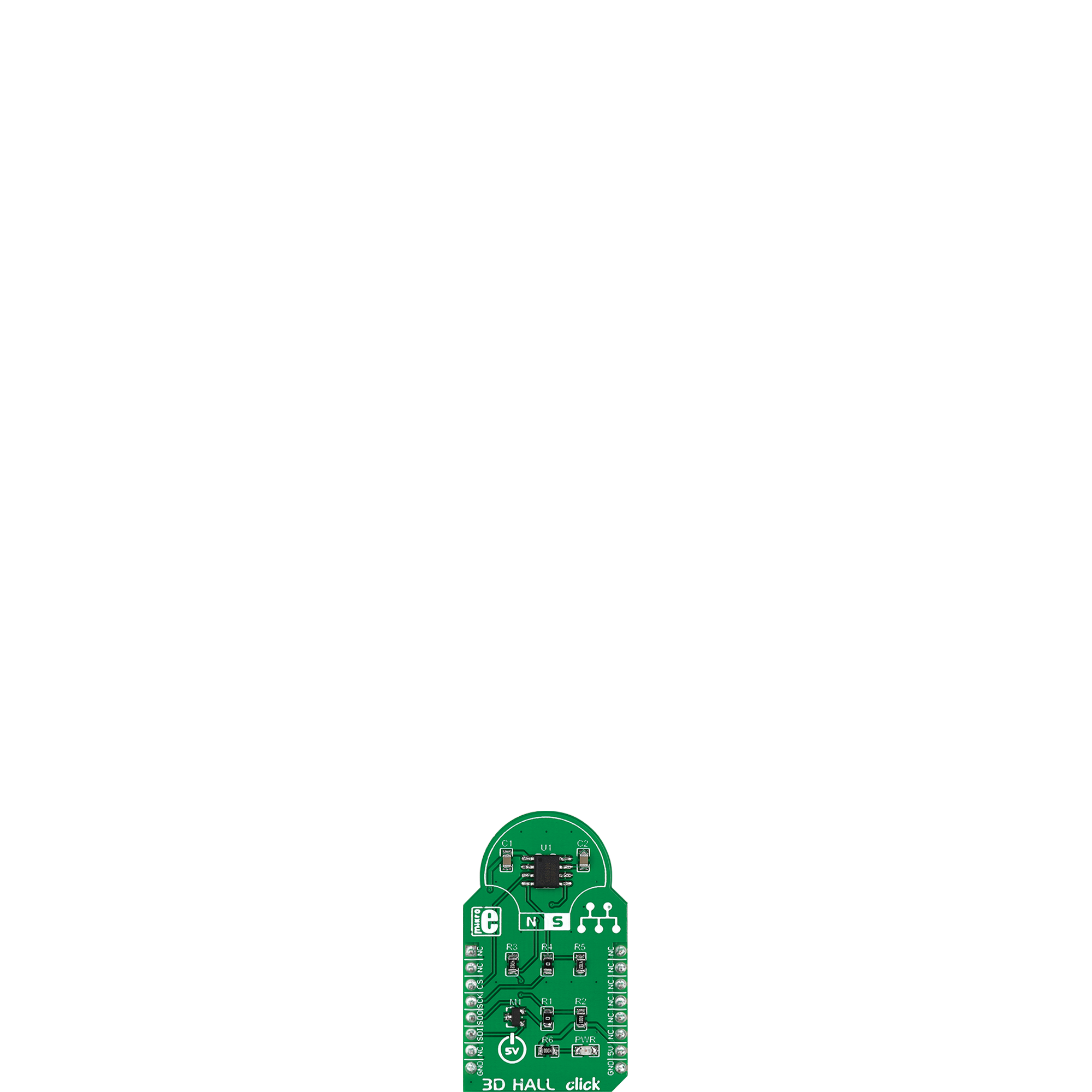
3D Hall Click
Dev. board
Nucleo-64 with STM32L073RZ MCU
Compiler
NECTO Studio
MCU
STM32L073RZ
Our primary objective is to provide a comprehensive 3D Hall sensor solution that combines the precision of three-dimensional magnetometry with the user-friendly features you need to explore and utilize magnetic data effectively
A
A
Hardware Overview
How does it work?
3D Hall Click is based on the MLX90333, a Triaxis® contactless position sensor from Melexis Technologies able to sense any magnet moving in its surroundings through the measurement and the processing of the three spatial components of the magnetic flux density vector (Bx, By, and Bz). The horizontal components (Bx and By) are sensed thanks to an Integrated Magneto-Concentrator (IMC), while the vertical component (Bz) is sensed through a conventional Hall plate.
Thanks to its excellent performance, the MLX90333 can accurately measure its rotational, linear, and 3D displacement. The MLX90333 features a 3D magnetometer mode for which the 3D information of the magnetic flux density is reported to a host controller through an SPI interface supporting the most common SPI mode, SPI Mode 1, with a maximum frequency of 20MHz. The output transfer characteristic is fully programmable (e.g., offset, gain, clamping levels,
linearity, thermal drift, filtering, range, and such) to match any specific requirement through end-of-line calibration. This Click board™ can be operated only with a 5V logic voltage level. The board must perform appropriate logic voltage level conversion before using MCUs with different logic levels. Also, it comes equipped with a library containing functions and an example code that can be used as a reference for further development.

Features overview
Development board
Nucleo-64 with STM32L073RZ MCU offers a cost-effective and adaptable platform for developers to explore new ideas and prototype their designs. This board harnesses the versatility of the STM32 microcontroller, enabling users to select the optimal balance of performance and power consumption for their projects. It accommodates the STM32 microcontroller in the LQFP64 package and includes essential components such as a user LED, which doubles as an ARDUINO® signal, alongside user and reset push-buttons, and a 32.768kHz crystal oscillator for precise timing operations. Designed with expansion and flexibility in mind, the Nucleo-64 board features an ARDUINO® Uno V3 expansion connector and ST morpho extension pin
headers, granting complete access to the STM32's I/Os for comprehensive project integration. Power supply options are adaptable, supporting ST-LINK USB VBUS or external power sources, ensuring adaptability in various development environments. The board also has an on-board ST-LINK debugger/programmer with USB re-enumeration capability, simplifying the programming and debugging process. Moreover, the board is designed to simplify advanced development with its external SMPS for efficient Vcore logic supply, support for USB Device full speed or USB SNK/UFP full speed, and built-in cryptographic features, enhancing both the power efficiency and security of projects. Additional connectivity is
provided through dedicated connectors for external SMPS experimentation, a USB connector for the ST-LINK, and a MIPI® debug connector, expanding the possibilities for hardware interfacing and experimentation. Developers will find extensive support through comprehensive free software libraries and examples, courtesy of the STM32Cube MCU Package. This, combined with compatibility with a wide array of Integrated Development Environments (IDEs), including IAR Embedded Workbench®, MDK-ARM, and STM32CubeIDE, ensures a smooth and efficient development experience, allowing users to fully leverage the capabilities of the Nucleo-64 board in their projects.

Microcontroller Overview
MCU Card / MCU

Architecture
ARM Cortex-M0
MCU Memory (KB)
192
Silicon Vendor
STMicroelectronics
Pin count
64
RAM (Bytes)
20480
You complete me!
Accessories
Click Shield for Nucleo-64 comes equipped with two proprietary mikroBUS™ sockets, allowing all the Click board™ devices to be interfaced with the STM32 Nucleo-64 board with no effort. This way, Mikroe allows its users to add any functionality from our ever-growing range of Click boards™, such as WiFi, GSM, GPS, Bluetooth, ZigBee, environmental sensors, LEDs, speech recognition, motor control, movement sensors, and many more. More than 1537 Click boards™, which can be stacked and integrated, are at your disposal. The STM32 Nucleo-64 boards are based on the microcontrollers in 64-pin packages, a 32-bit MCU with an ARM Cortex M4 processor operating at 84MHz, 512Kb Flash, and 96KB SRAM, divided into two regions where the top section represents the ST-Link/V2 debugger and programmer while the bottom section of the board is an actual development board. These boards are controlled and powered conveniently through a USB connection to program and efficiently debug the Nucleo-64 board out of the box, with an additional USB cable connected to the USB mini port on the board. Most of the STM32 microcontroller pins are brought to the IO pins on the left and right edge of the board, which are then connected to two existing mikroBUS™ sockets. This Click Shield also has several switches that perform functions such as selecting the logic levels of analog signals on mikroBUS™ sockets and selecting logic voltage levels of the mikroBUS™ sockets themselves. Besides, the user is offered the possibility of using any Click board™ with the help of existing bidirectional level-shifting voltage translators, regardless of whether the Click board™ operates at a 3.3V or 5V logic voltage level. Once you connect the STM32 Nucleo-64 board with our Click Shield for Nucleo-64, you can access hundreds of Click boards™, working with 3.3V or 5V logic voltage levels.

Used MCU Pins
mikroBUS™ mapper
Take a closer look
Click board™ Schematic

Step by step
Project assembly
Start by selecting your development board and Click board™. Begin with the Nucleo-64 with STM32L073RZ MCU as your development board.


Software Support
Library Description
This library contains API for 3D Hall Click driver.
Key functions:
c3dhall_read_all_data- Read 8 bytes data from sensor functionc3dhall_calculate_angle- Calculate angle function
Open Source
Code example
The complete application code and a ready-to-use project are available through the NECTO Studio Package Manager for direct installation in the NECTO Studio. The application code can also be found on the MIKROE GitHub account.
/*!
 * \file
 * \brief c3DHall Click example
 *
 * # Description
 * This application use to determine angle position.
 *
 * The demo application is composed of two sections :
 *
 * ## Application Init
 * Initialization driver enable's - SPI and start write log.
 *
 * ## Application Task
 * This is a example which demonstrates the use of 3D Hall Click board.
 * 3D Hall Click communicates with register via SPI by read data from register
 * and calculate Alpha and Beta angle position.
 * Results are being sent to the Usart Terminal where you can track their changes.
 * All data logs on usb uart.
 *
 * ## NOTE
 * The maximal SPI Clock frequency for MLX90333 sensor is about 430 Khz.
 * If you are expiriencing issues, please try to lower MCU's main clock frequency.
 *
 * \author MikroE Team
 *
 */
// ------------------------------------------------------------------- INCLUDES

#include "board.h"
#include "log.h"
#include "c3dhall.h"

// ------------------------------------------------------------------ VARIABLES

static c3dhall_t c3dhall;
static log_t logger;

void application_init ( void )
{
    log_cfg_t log_cfg;
    c3dhall_cfg_t cfg;
    /**
     * Logger initialization.
     * Default baud rate: 115200
     * Default log level: LOG_LEVEL_DEBUG
     * @note If USB_UART_RX and USB_UART_TX
     * are defined as HAL_PIN_NC, you will
     * need to define them manually for log to work.
     * See @b LOG_MAP_USB_UART macro definition for detailed explanation.
     */
    LOG_MAP_USB_UART( log_cfg );
    log_init( &logger, &log_cfg );
    log_info( &logger, "---- Application Init ----" );

    //  Click initialization.

    c3dhall_cfg_setup( &cfg );
    C3DHALL_MAP_MIKROBUS( cfg, MIKROBUS_1 );
    c3dhall_init( &c3dhall, &cfg );
    Delay_100ms( );
}

void application_task ( void )
{
    c3dhall_all_data_t all_data;

    uint8_t angle_alpha;
    uint8_t angle_beta;

    c3dhall_read_all_data( &c3dhall, &all_data );
    Delay_100ms( );

    if ( ( all_data.data_error ) == C3DHALL_NO_ERRORS )
    {
        angle_alpha = c3dhall_calculate_angle( &c3dhall, all_data.data_angle_a );
        angle_beta = c3dhall_calculate_angle( &c3dhall, all_data.data_angle_b );

        log_printf( &logger, "     Alpha : %u\r\n", ( uint16_t ) angle_alpha );

        log_printf( &logger, "     Beta  : %u\r\n", ( uint16_t ) angle_beta );

        log_printf( &logger, "-------------------------\r\n", angle_beta );
    }
    else
    {
        if ( all_data.data_error == C3DHALL_F_ADCMONITOR )
            log_printf( &logger, "       ADC Failure       \r\n" );
        else if ( all_data.data_error == C3DHALL_F_ADCSATURA )
            log_printf( &logger, "    Electrical failure   \r\n"  );
        else if ( all_data.data_error == C3DHALL_F_GAINTOOLOW )
            log_printf( &logger, "    Gain code is less    \r\n" );
        else if ( all_data.data_error == C3DHALL_F_GAINTOOHIGH )
            log_printf( &logger, "   Gain code is greater  \r\n" );
        else if ( all_data.data_error == C3DHALL_F_NORMTOOLOW )
            log_printf( &logger, "   Fast norm below 30   \r\n" );
        else if ( all_data.data_error == C3DHALL_F_FIELDTOOLOW )
            log_printf( &logger, "     The norm is less    \r\n" );
        else if ( all_data.data_error == C3DHALL_F_FIELDTOOHIGH )
            log_printf( &logger, "   The norm is greater   \r\n" );
        else if ( all_data.data_error == C3DHALL_F_ROCLAMP )
            log_printf( &logger, "  Analog Chain Rough off \r\n" );
        else if ( all_data.data_error == C3DHALL_F_DEADZONEALPHA )
            log_printf( &logger, " Angle ALPHA in deadzone \r\n" );
        else if ( all_data.data_error == C3DHALL_F_DEADZONEBETA )
            log_printf( &logger, "  Angle BETA in deadzone \r\n" );
        else if ( all_data.data_error == C3DHALL_MULTIPLE_ERRORS )
            log_printf( &logger, "   More than one error   \r\n" );
        else
            log_printf( &logger, "      Unknown error      \r\n" );

        log_printf( &logger, "-------------------------\r\n" );
        Delay_1sec( );
    }
}

int main ( void )
{
    /* Do not remove this line or clock might not be set correctly. */
    #ifdef PREINIT_SUPPORTED
    preinit();
    #endif

    application_init( );

    for ( ; ; )
    {
        application_task( );
    }

    return 0;
}


// ------------------------------------------------------------------------ END
Additional Support
Resources
Category:Magnetic


