Experience intuitive navigation with CY8CMBR3106S-LQXI and STM32L152RE
Quadruple touch, one slide
Published Oct 08, 2024
Click board™
Cap Touch 5 Click
Dev. board
Nucleo 64 with STM32L152RE MCU
Compiler
NECTO Studio
MCU
STM32L152RE
Discover a game-changing interface, seamlessly integrating four touch buttons and a slider. Explore its engineering marvel, transforming user interaction across diverse applications
A
A
Hardware Overview
How does it work?
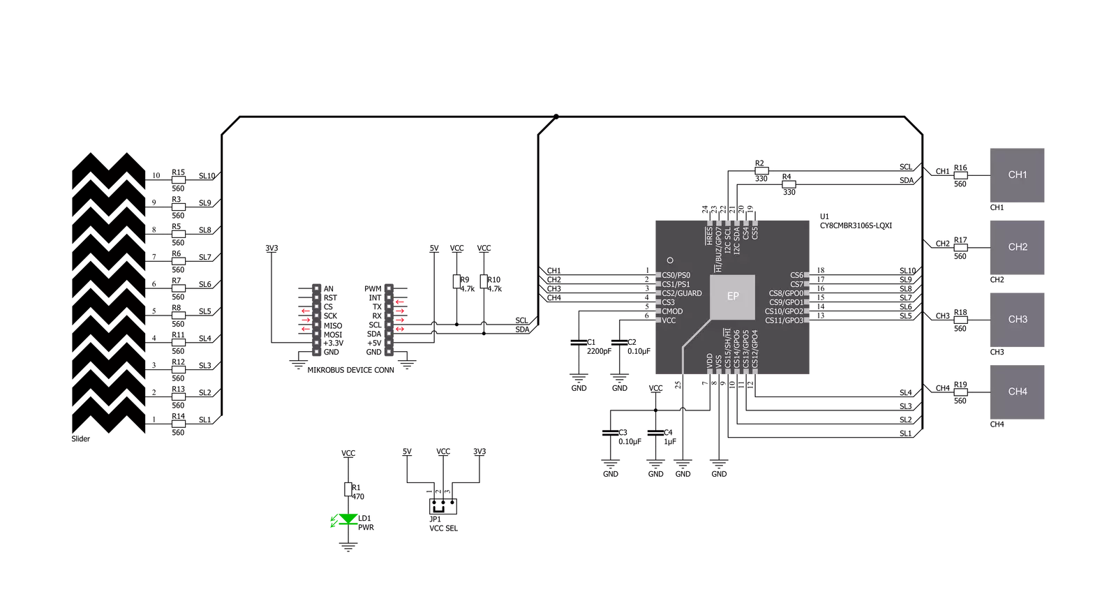
Cap Touch 5 Click is based on the CY8CMBR3106S-LQXI, a CapSense® Express™ controller from Infineon, which has an advanced analog sensing channel and the Capacitive Sigma Delta PLUS (CSD PLUS) sensing algorithm, which delivers a signal-to-noise ratio (SNR) of greater than 100:1 to ensure touch accuracy even in extremely noisy environments. This controller is enabled with Infineon’s SmartSense™ Auto-tuning algorithm, which compensates for manufacturing variations and dynamically monitors and maintains optimal sensor performance in all environmental conditions. In addition, SmartSense Auto-tuning enables a faster time-to-market by eliminating the
time-consuming manual tuning efforts during development and production ramp-up. Advanced features like LED brightness control, proximity sensing, and system diagnostics save development time. These controllers enable robust liquid-tolerant designs by eliminating false touches due to mist, water droplets, or streaming water. The CapSense controller locks up the user interface in firmware to prevent touch inputs in streaming water. Additionally, it implements the advanced noise immunity algorithm, EMC, for stable operation in extremely noisy conditions. Besides that, it is also perfectly suited for low-power applications, such as those operated by a
battery, when a capacitive sensing controller with ultra-low average power consumption must be selected. The CY8CMBR3106S-LQXI controller draws an average current of 22µA per sensor. The Cap Touch 5 Click supports four CapSense buttons. Its sensitivity can be specified individually for each CapSense button and slider. Higher sensitivity values can be used for thick overlays or small button diameters, while lower sensitivity values should be used for large buttons or thin overlays to minimize power consumption. Therefore, this Click board™ comes without the overlay, so it is up to the user to choose the desired application and implementation.


Features overview
Development board
Nucleo-64 with STM32L152RE MCU offers a cost-effective and adaptable platform for developers to explore new ideas and prototype their designs. This board harnesses the versatility of the STM32 microcontroller, enabling users to select the optimal balance of performance and power consumption for their projects. It accommodates the STM32 microcontroller in the LQFP64 package and includes essential components such as a user LED, which doubles as an ARDUINO® signal, alongside user and reset push-buttons, and a 32.768kHz crystal oscillator for precise timing operations. Designed with expansion and flexibility in mind, the Nucleo-64 board features an ARDUINO® Uno V3 expansion connector and ST morpho extension pin
headers, granting complete access to the STM32's I/Os for comprehensive project integration. Power supply options are adaptable, supporting ST-LINK USB VBUS or external power sources, ensuring adaptability in various development environments. The board also has an on-board ST-LINK debugger/programmer with USB re-enumeration capability, simplifying the programming and debugging process. Moreover, the board is designed to simplify advanced development with its external SMPS for efficient Vcore logic supply, support for USB Device full speed or USB SNK/UFP full speed, and built-in cryptographic features, enhancing both the power efficiency and security of projects. Additional connectivity is
provided through dedicated connectors for external SMPS experimentation, a USB connector for the ST-LINK, and a MIPI® debug connector, expanding the possibilities for hardware interfacing and experimentation. Developers will find extensive support through comprehensive free software libraries and examples, courtesy of the STM32Cube MCU Package. This, combined with compatibility with a wide array of Integrated Development Environments (IDEs), including IAR Embedded Workbench®, MDK-ARM, and STM32CubeIDE, ensures a smooth and efficient development experience, allowing users to fully leverage the capabilities of the Nucleo-64 board in their projects.

Microcontroller Overview
MCU Card / MCU

Architecture
ARM Cortex-M3
MCU Memory (KB)
512
Silicon Vendor
STMicroelectronics
Pin count
64
RAM (Bytes)
81920
You complete me!
Accessories
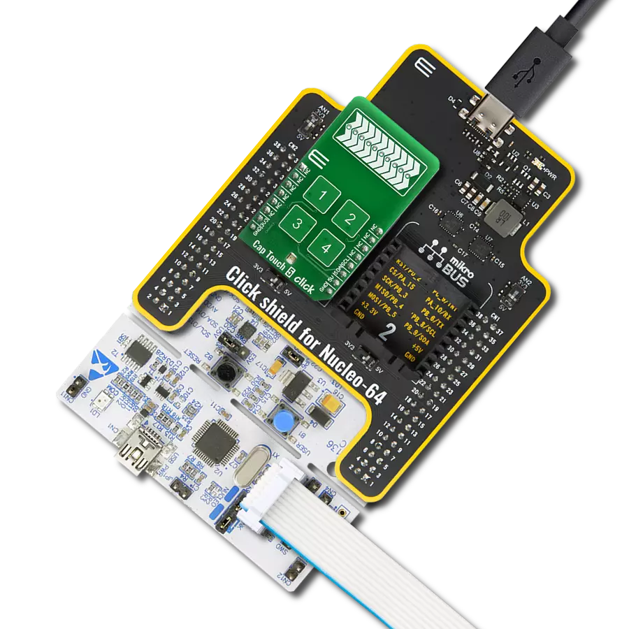
Click Shield for Nucleo-64 comes equipped with two proprietary mikroBUS™ sockets, allowing all the Click board™ devices to be interfaced with the STM32 Nucleo-64 board with no effort. This way, Mikroe allows its users to add any functionality from our ever-growing range of Click boards™, such as WiFi, GSM, GPS, Bluetooth, ZigBee, environmental sensors, LEDs, speech recognition, motor control, movement sensors, and many more. More than 1537 Click boards™, which can be stacked and integrated, are at your disposal. The STM32 Nucleo-64 boards are based on the microcontrollers in 64-pin packages, a 32-bit MCU with an ARM Cortex M4 processor operating at 84MHz, 512Kb Flash, and 96KB SRAM, divided into two regions where the top section represents the ST-Link/V2 debugger and programmer while the bottom section of the board is an actual development board. These boards are controlled and powered conveniently through a USB connection to program and efficiently debug the Nucleo-64 board out of the box, with an additional USB cable connected to the USB mini port on the board. Most of the STM32 microcontroller pins are brought to the IO pins on the left and right edge of the board, which are then connected to two existing mikroBUS™ sockets. This Click Shield also has several switches that perform functions such as selecting the logic levels of analog signals on mikroBUS™ sockets and selecting logic voltage levels of the mikroBUS™ sockets themselves. Besides, the user is offered the possibility of using any Click board™ with the help of existing bidirectional level-shifting voltage translators, regardless of whether the Click board™ operates at a 3.3V or 5V logic voltage level. Once you connect the STM32 Nucleo-64 board with our Click Shield for Nucleo-64, you can access hundreds of Click boards™, working with 3.3V or 5V logic voltage levels.

Used MCU Pins
mikroBUS™ mapper
Take a closer look
Click board™ Schematic
Step by step
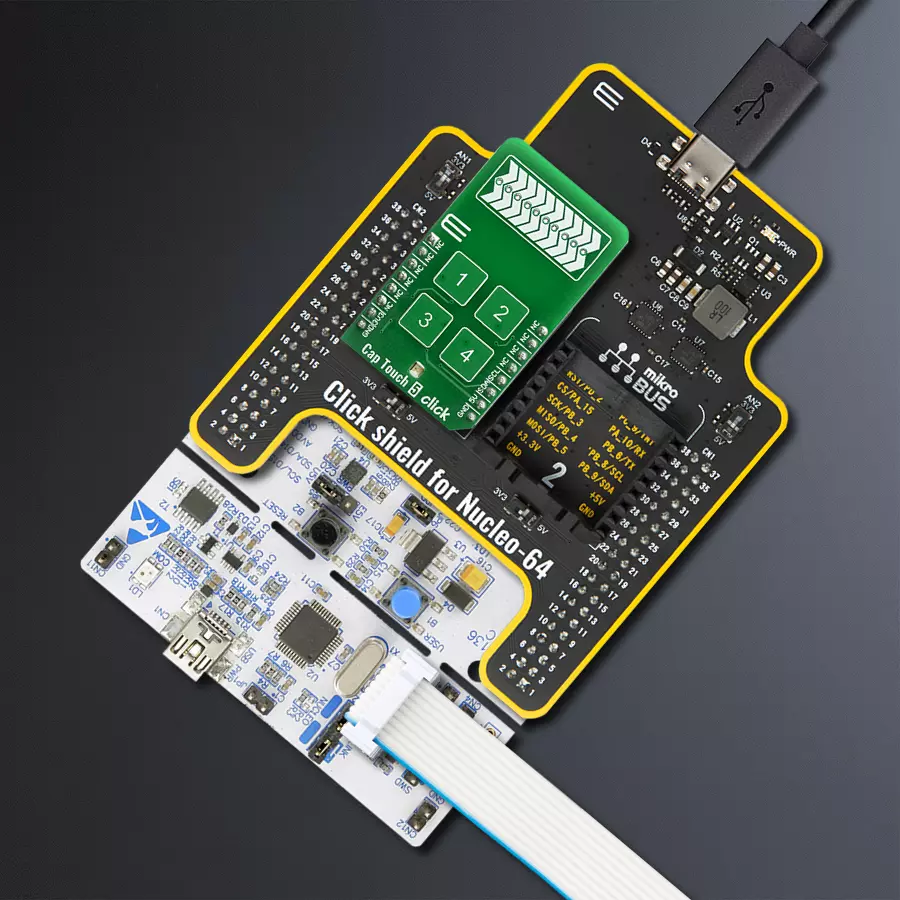
Project assembly
Start by selecting your development board and Click board™. Begin with the Nucleo 64 with STM32L152RE MCU as your development board.


Track your results in real time
Application Output
1. Application Output - In Debug mode, the 'Application Output' window enables real-time data monitoring, offering direct insight into execution results. Ensure proper data display by configuring the environment correctly using the provided tutorial.

2. UART Terminal - Use the UART Terminal to monitor data transmission via a USB to UART converter, allowing direct communication between the Click board™ and your development system. Configure the baud rate and other serial settings according to your project's requirements to ensure proper functionality. For step-by-step setup instructions, refer to the provided tutorial.

3. Plot Output - The Plot feature offers a powerful way to visualize real-time sensor data, enabling trend analysis, debugging, and comparison of multiple data points. To set it up correctly, follow the provided tutorial, which includes a step-by-step example of using the Plot feature to display Click board™ readings. To use the Plot feature in your code, use the function: plot(*insert_graph_name*, variable_name);. This is a general format, and it is up to the user to replace 'insert_graph_name' with the actual graph name and 'variable_name' with the parameter to be displayed.

Software Support
Library Description
This library contains API for Cap Touch 5 Click driver.
Key functions:
captouch5_read_button_status- This function reads button statuscaptouch5_read_slider_position- This function reads slider position
Open Source
Code example
The complete application code and a ready-to-use project are available through the NECTO Studio Package Manager for direct installation in the NECTO Studio. The application code can also be found on the MIKROE GitHub account.
/*!
 * \file
 * \brief CapTouch5 Click example
 *
 * # Description
 * This demo app demonstrates basic functionality of CapTouch 5 Click
 *
 * The demo application is composed of two sections :
 *
 * ## Application Init
 * Initializes I2C module and driver, tests communication and configures device
 *
 * ## Application Task
 * Waiting for touch sensor to detect something and then logs what is touched
 *
 * *note:*
 * Click will go to sleep if doesn't get any command in 340ms
 * When you start device try restarting your board few times to start device
 *
 * \author MikroE Team
 *
 */
// ------------------------------------------------------------------- INCLUDES

#include "board.h"
#include "log.h"
#include "captouch5.h"

// ------------------------------------------------------------------ VARIABLES

static captouch5_t captouch5;
static log_t logger;

static T_CAPTOUCH5_BUTTONS buttons;
static T_CAPTOUCH5_DEVICE_CONFIG device_cfg;
static uint8_t state_check;

// ------------------------------------------------------- ADDITIONAL FUNCTIONS

void captouch5_read_buttons(  )
{
    uint8_t press = 0;

    if ( buttons.button1 == CAPTOUCH5_BUTTON_PRESSED )
    {
        log_info( &logger, "Button 1 : pressed" );
        press = 1;
    }

    if ( buttons.button2 == CAPTOUCH5_BUTTON_PRESSED )
    {
        log_info( &logger, "Button 2 : pressed" );
        press = 1;
    }

    if ( buttons.button3 == CAPTOUCH5_BUTTON_PRESSED )
    {
        log_info( &logger, "Button 3 : pressed" );
        press = 1;
    }

    if (buttons.button4 == CAPTOUCH5_BUTTON_PRESSED)
    {
        log_info( &logger, "Button 4 : pressed" );
        press = 1;
    }

    if (press)
    {
        log_printf( &logger, "\r\n" );
        state_check = 1;
        press = 0;
    }
}


// ------------------------------------------------------ APPLICATION FUNCTIONS

void application_init ( void )
{
    log_cfg_t log_cfg;
    captouch5_cfg_t cfg;

    /**
     * Logger initialization.
     * Default baud rate: 115200
     * Default log level: LOG_LEVEL_DEBUG
     * @note If USB_UART_RX and USB_UART_TX
     * are defined as HAL_PIN_NC, you will
     * need to define them manually for log to work.
     * See @b LOG_MAP_USB_UART macro definition for detailed explanation.
     */
    LOG_MAP_USB_UART( log_cfg );
    log_init( &logger, &log_cfg );
    log_info( &logger, "---- Application Init ----" );

    //  Click initialization.

    captouch5_cfg_setup( &cfg );
    CAPTOUCH5_MAP_MIKROBUS( cfg, MIKROBUS_1 );
    captouch5_init( &captouch5, &cfg );
    captouch5_default_cfg ( &captouch5, &device_cfg );
}

void application_task ( void )
{
    uint16_t temp_byte;
    uint16_t last_temp;
    uint8_t temp_slider;

    state_check = 0;

    if ( CAPTOUCH5_ERROR == captouch5_process( &captouch5 ) )
    {
        log_printf( &logger, "***** ERROR *****" );
        state_check = 1;
        return;
    }

    temp_byte = captouch5_read_slider_position( &captouch5 );
    captouch5_read_button_status( &captouch5, &buttons );

    if ( temp_byte != last_temp )
    {
        log_printf( &logger, "Slider position value: %u \r\n", temp_byte );
        last_temp = temp_byte;
        state_check = 1;
    }

    captouch5_read_buttons(  );

    Delay_ms ( 100 );

    if ( state_check == 1 )
    {
        log_info( &logger, "--- Waiting for command ---\r\n" );
    }
}

int main ( void )
{
    /* Do not remove this line or clock might not be set correctly. */
    #ifdef PREINIT_SUPPORTED
    preinit();
    #endif

    application_init( );

    for ( ; ; )
    {
        application_task( );
    }

    return 0;
}

// ------------------------------------------------------------------------ END


